
The Gap Between Physical Reality and Schematic Theory
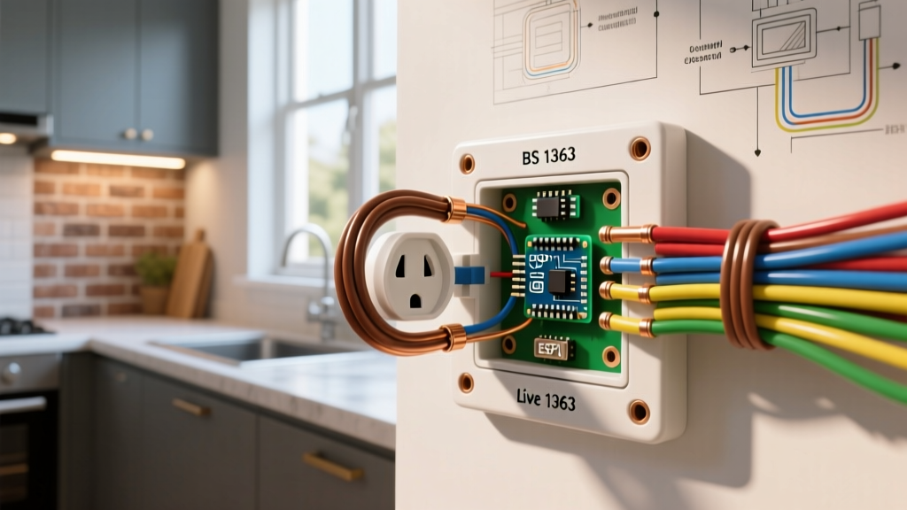
When a light fixture fails to illuminate, flickers unpredictably, or trips a breaker immediately upon toggling, the physical wires inside the junction box rarely tell the whole story. In 2026, with the proliferation of smart home ecosystems and complex multi-location dimming circuits, relying purely on visual wire tracing is a recipe for misdiagnosis. This is where electrical wiring diagrams become your primary diagnostic instrument. A schematic abstracts the physical mess of 14 AWG copper into logical pathways, allowing you to isolate the exact node of failure—whether it is a degraded internal contact, a miswired traveler, or a missing neutral return.
Troubleshooting without a diagram is like navigating a foreign city without a map; you might eventually find your destination, but you will waste hours taking wrong turns. By cross-referencing the physical voltage readings at the switch box with the logical flow of the schematic, you can pinpoint open circuits, short circuits, and code violations with surgical precision.
Standard Schematic Symbols for Switchgear
Before connecting a multimeter, you must decode the diagram. The National Electrical Manufacturers Association (NEMA) and standard architectural blueprints utilize specific glyphs to represent switch states and pole configurations. Misinterpreting a Single Pole Double Throw (SPDT) symbol as a standard Single Pole switch will immediately lead to incorrect traveler mapping in 3-way circuits.
| Symbol / Abbreviation | Technical Name | Physical Equivalent | Common Diagnostic Use Case |
|---|---|---|---|
| SPST | Single Pole, Single Throw | Standard 2-terminal wall switch | Basic on/off room lighting; 1 hot in, 1 switched hot out. |
| SPDT | Single Pole, Double Throw | 3-Way Switch | Multi-location control; 1 common terminal, 2 traveler terminals. |
| DPDT | Double Pole, Double Throw | 4-Way Switch | Intermediate multi-location; 2 pairs of travelers passing through. |
| NO / NC | Normally Open / Closed | Relays, Occupancy Sensors | Automated lighting circuits; diagnosing sensor failure states. |
The 4-Step Diagnostic Protocol
Step 1: Verify Power and Isolate the Circuit
Never trust a standard toggle switch to isolate power. Use a non-contact voltage tester (NCVT) to scan the faceplate, then remove the cover and test the terminal screws. According to OSHA electrical safety guidelines, you must verify your tester on a known live source before and after testing the target circuit to ensure the tool's battery hasn't failed mid-diagnosis. A premium tool like the Klein Tools NCVT-3IR (approx. $38) detects voltage through shielded wires and ignores phantom static, reducing false positives.
Step 2: Map Physical Wires to the Schematic
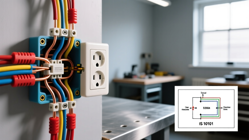
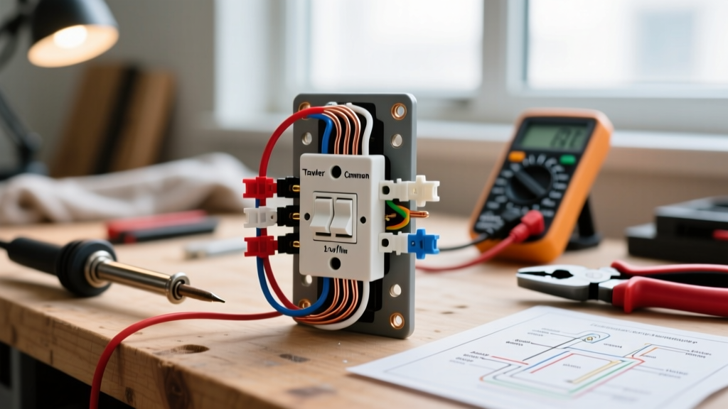
Once power is confirmed dead at the breaker, map the physical wires to your electrical wiring diagram. In a standard 15-amp residential circuit using 14/2 NM-B Romex, the black wire is your ungrounded conductor (Hot/Line), the white is the grounded conductor (Neutral), and the bare copper is the equipment grounding conductor. If you are looking at a 3-way switch box fed with 14/3 NM-B, the red and black wires are typically your travelers, while the white wire serves as the neutral or a re-identified hot feed. Use blue painter's tape to label the wires exactly as they appear on the schematic (e.g., "Line," "Load," "T1," "T2").
Step 3: Continuity Testing the Switch Mechanism
Set your multimeter (such as the industry-standard Fluke 117 True-RMS, retailing around $220) to the Ohms (Ω) or continuity setting. As detailed in Fluke's guide on testing for continuity, place one probe on the common terminal and the other on the traveler or switched output. A healthy closed switch will read less than 1.0 Ω. An open switch will display "OL" (Open Loop). If your diagram indicates an SPST switch but you measure continuity regardless of the toggle position, the internal contacts have welded together—a critical fire hazard requiring immediate replacement.
Step 4: Voltage Drop and Load Verification
Restore power and measure voltage at the switch terminals. Hot to Ground should read 120V (±5%). If you measure Hot to Neutral and get a reading between 60V and 90V, you are likely reading phantom voltage caused by capacitive coupling in long parallel wire runs, or you have a high-resistance joint (a failing wire nut) upstream. Use the multimeter's LoZ (Low Impedance) mode to eliminate phantom voltage ghosting.
Common Diagram-to-Reality Mismatches (Failure Modes)
The 3-Way Traveler Transposition
The most frequent DIY failure in multi-location lighting is the miswired 3-way switch. On your electrical wiring diagram, the common terminal (usually the black or copper-colored screw) must connect to either the Line source or the Load fixture. The two brass screws are for the travelers. If a previous installer swapped the Line wire with a Traveler wire, the circuit will exhibit a bizarre failure mode: the light will only turn on if the opposing switch is in the "up" position. The diagram instantly reveals this error by showing that the source voltage is entering a traveler terminal instead of the common node.
The "Switched Neutral" Code Violation
Older homes (pre-1970s) sometimes feature a dangerous wiring method where the switch interrupts the neutral wire instead of the hot wire. In this scenario, the light turns off, but the fixture socket remains energized at 120V. If your wiring diagram shows the switch on the white neutral leg rather than the black hot leg, you have identified a severe shock hazard. Diagnose this by testing the light socket with the switch in the "OFF" position; if you read 120V from the socket's hot tab to ground, the neutral is being switched. The entire circuit must be rewired to comply with modern safety standards.
Smart Switch Neutral Starvation
Upgrading to smart switches in 2026 often exposes missing neutrals in older switch boxes. Smart switches require a constant 120V power source to operate their internal Wi-Fi/Zigbee radios, even when the light is off. If your diagram lacks a neutral bundle in the switch box, standard smart switches (like the Leviton Decora Smart D26HD, approx. $55) will fail to power on or will cause LED fixtures to ghost-flash. The solution is either pulling a new 14/2 neutral feed or utilizing a specialized no-neutral switch like the Lutron Caseta PD-5S-DV (approx. $65), which safely bleeds a micro-current through the load without requiring a neutral wire.
2026 NEC Code Considerations for Switch Boxes
Code Alert: Under NEC Article 404.2(C), as enforced in the 2023 and 2026 code cycles, a grounded circuit conductor (neutral) must be provided at nearly all switch locations controlling lighting loads. This was implemented specifically to support advanced lighting controls, occupancy sensors, and smart home hubs. If you are troubleshooting a newly constructed home and find a switch box without a neutral, the installation is non-compliant and must be corrected by the contractor. For more information, consult the National Fire Protection Association (NFPA) NEC portal.
Essential Diagnostic Tooling & Costs
Accurate troubleshooting requires professional-grade instrumentation. Cheap analog testers cannot differentiate between phantom voltage and true fault conditions. Below is the recommended 2026 diagnostic loadout for switchgear analysis:
| Tool Category | Recommended Model | Est. Cost (2026) | Primary Diagnostic Function |
|---|---|---|---|
| True-RMS Multimeter | Fluke 117 Electricians Multimeter | $210 - $230 | Accurate AC voltage, continuity, and LoZ phantom voltage elimination. |
| NCVT Tester | Klein Tools NCVT-3IR | $35 - $45 | Safe, non-invasive verification of de-energized circuits before physical contact. |
| Receptacle Analyzer | Amprobe AT-3500 | $80 - $95 | Testing downstream receptacles to verify if a switched half-hot is wired correctly. |
| Tone & Probe Kit | Fluke AT-820 | $350 - $380 | Tracing hidden travelers inside finished walls when diagrams are missing or inaccurate. |
By systematically combining the logical roadmap of an electrical wiring diagram with empirical data from precision testing tools, you eliminate guesswork. Whether you are diagnosing a simple SPST toggle failure or untangling a 4-way smart dimmer network, the schematic remains your most powerful troubleshooting asset.