
Why Proper Outlet Replacement Matters
Replacing an electrical outlet is widely considered the gateway DIY electrical project. However, according to the Consumer Product Safety Commission (CPSC), faulty receptacles and improper wiring connections are leading contributors to residential electrical fires. A loose terminal screw or a degraded backstab connection can create high-resistance arcing, generating enough heat to ignite surrounding drywall paper and wood framing.
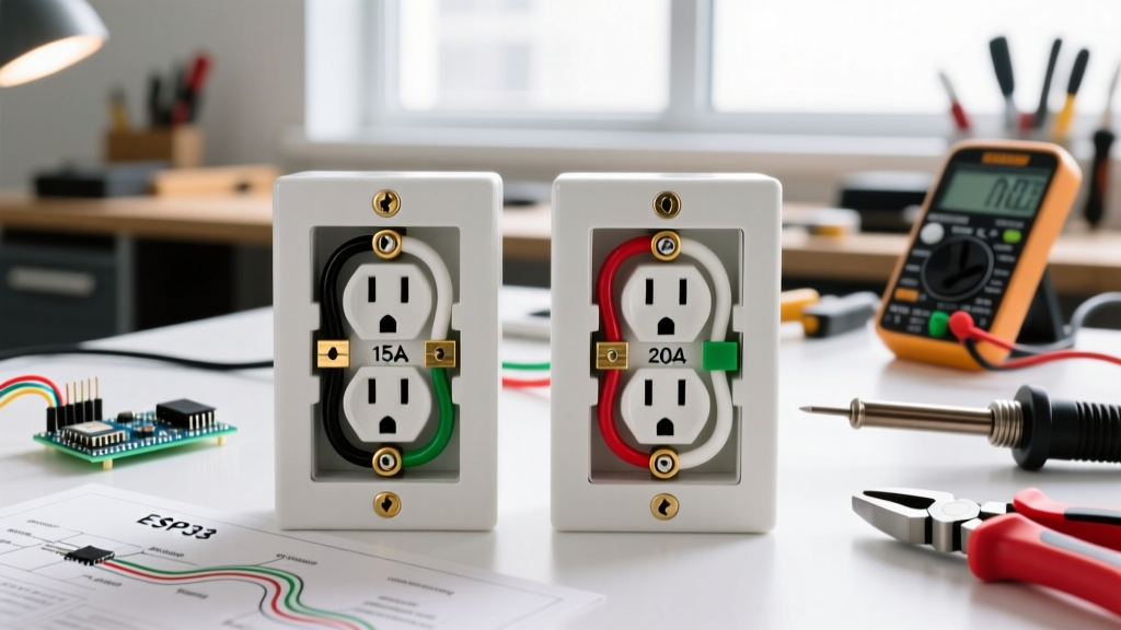
This comprehensive tutorial focuses specifically on replacing a standard 15-Amp, 125-Volt NEMA 5-15R duplex receptacle. We will bypass generic advice and focus on the exact measurements, torque specifications, and National Electrical Code (NEC) requirements necessary for a safe, professional-grade installation in 2026.
Critical Safety Warning: Never assume a wall switch or a previous homeowner's labeling is accurate. Always verify the absence of voltage at the receptacle terminals using a calibrated tester before making physical contact with any conductors.
Essential Tools & Materials for the Job
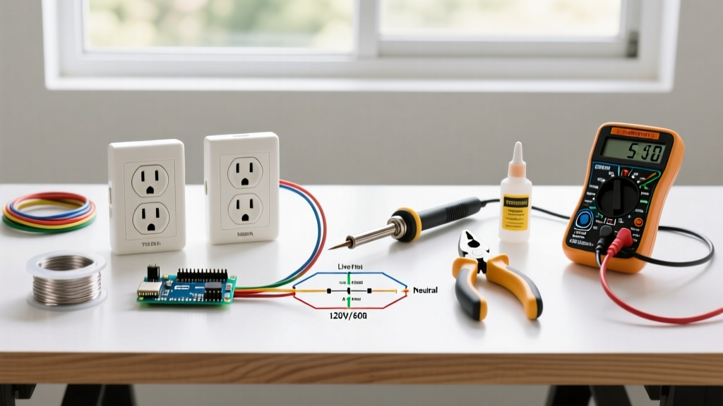
Professional electricians rely on specific, high-tolerance tools to ensure connections do not degrade over time. Below is the exact toolkit required for this project, including current estimated retail pricing.
| Category | Recommended Model | Purpose | Est. Cost (2026) |
|---|---|---|---|
| Voltage Tester | Klein Tools NCVT-2 | Dual-range non-contact voltage detection | $28.00 |
| Wire Stripper | Klein Tools 11054 | Precision stripping for 14 & 12 AWG solid copper | $32.00 |
| Receptacle | Leviton 5248-W | 15A Tamper-Resistant (TR) Duplex, Commercial Spec Grade | $3.50 |
| Terminal Torque | Wiha 61090 TorqueVario | Ensures NEC 110.14(D) compliance (inch-pound accuracy) | $85.00 |
| Plug Tester | Gardner Bender GFI-3501 | Verifies wiring sequence and GFCI tripping | $12.00 |
Phase 1: Safety & Lockout/Tagout (LOTO)
Before touching a single screw, you must isolate the circuit. The Occupational Safety and Health Administration (OSHA) mandates Lockout/Tagout procedures in commercial settings, and the exact same discipline applies to residential DIY work.
- Identify the Breaker: Locate the correct breaker in your main service panel. If the panel is unlabeled, plug a lamp into the target outlet and turn breakers off one by one until the lamp dies.
- Apply LOTO: Place a physical padlock or a heavy-duty zip-tie with a warning tag on the breaker handle. This prevents another household member from accidentally flipping the power back on while your hands are inside the junction box.
- Verify Zero Energy: Insert the probes of a multimeter or use your Klein NCVT-2 on both the top and bottom terminal screws of the existing outlet. Test a known live circuit first to ensure your tester's battery is functioning.
Phase 2: Removal & Configuration Inspection
Unscrew the center mounting screw of the faceplate, then remove the two 6-32 machine screws securing the top and bottom mounting straps to the junction box. Gently pull the receptacle out.
Document the Existing Wiring
Before disconnecting any wires, take a high-resolution photo with your smartphone. Pay close attention to the following:
- Line vs. Load: If there are two cables entering the box (two blacks, two whites, two grounds), one set is the 'Line' (power from the panel) and the other is the 'Load' (power feeding downstream outlets).
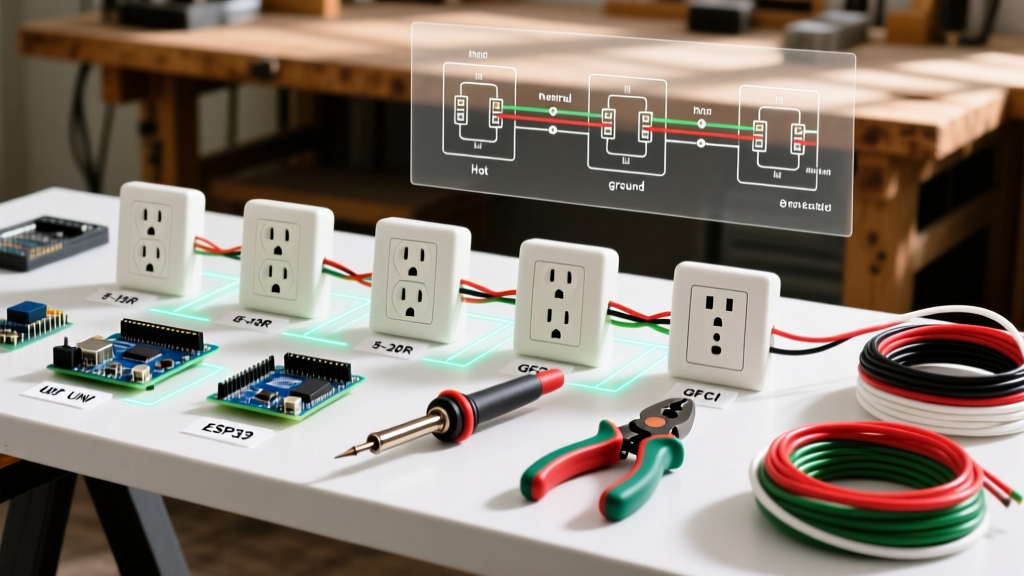
- Split Receptacles: Look at the brass side of the old receptacle. Is the small metal fin (break-off tab) between the top and bottom brass screws missing? If so, this is a split-wired outlet, typically controlled by a wall switch on the top half and always-hot on the bottom. You must break the tab on your new Leviton 5248-W to match this configuration.
Phase 3: Wire Preparation & Connection
The longevity of your outlet relies entirely on the quality of the copper-to-brass connection. The National Fire Protection Association (NFPA) updates the NEC regularly, and modern code strictly enforces connection integrity.
Step-by-Step Stripping and Looping
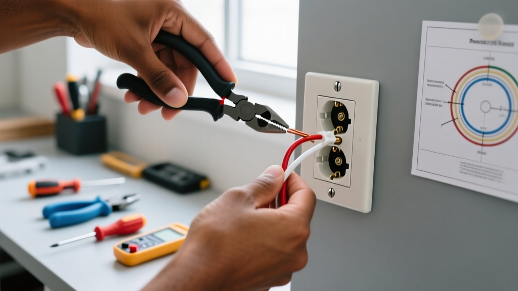
- Strip to Exact Length: Use the 14 AWG or 12 AWG hole on your Klein 11054 strippers. The bare copper should extend exactly 3/4 of an inch past the insulation jacket. Any less, and the screw head will bite into the plastic insulation; any more, and exposed live copper will sit outside the terminal plate, creating a shock hazard.
- Form the Shepherd's Hook: Using needle-nose pliers, bend the stripped wire into a tight, 180-degree hook.
- Route Clockwise: Hook the wire around the terminal screw in a clockwise direction. As you tighten the screw clockwise, the loop will naturally cinch tighter around the shaft. If routed counter-clockwise, the tightening motion will push the wire out from under the screw head.
- Torque the Screw: While most DIYers tighten by feel, NEC 110.14(D) requires connections to be torqued to the manufacturer's specifications. For a standard Leviton 15A receptacle, the target torque is 14 to 16 inch-pounds.
The Connection Method Debate: Backstab vs. Side-Wire vs. Screw-Clamp
Beginners often default to the push-in 'backstab' holes on the back of cheap receptacles. This is a critical error. Below is a comparison of the three primary termination methods.
| Method | Mechanism | Reliability & Code Stance |
|---|---|---|
| Backstab (Push-In) | Spring-loaded internal clip grips 14 AWG wire | Poor. Prone to thermal expansion/contraction loosening. High failure rate. Avoid entirely. |
| Side-Wire (Screw Loop) | Wire wrapped around terminal screw | Excellent. The industry standard. Provides maximum surface area contact and mechanical strength when torqued correctly. |
| Back-Wire (Screw-Clamp) | Wire inserted into rear hole, clamped by screw plate | Superior. Found on Spec-Grade and Commercial receptacles. Fastest and most secure method; no loop forming required. |
Phase 4: Grounding and Box Bonding
The bare copper (or green) grounding wire must be connected to the green grounding screw on the receptacle. If you have a metal junction box, the ground wire must also bond to the box itself, typically via a green 10-32 grounding screw threaded into the back of the box. Use a wire nut and a pigtail to connect the incoming ground, the downstream ground, and the receptacle pigtail together if necessary.
Phase 5: Securing & Final Testing
Carefully fold the wires into the back of the junction box. The ideal folding technique is an 'S-curve' or accordion fold, pushing the ground wires to the very back, followed by the whites (neutrals), and finally the blacks (hots) near the front. This prevents the hot wires from being pinched against the sharp metal edges of the box by the receptacle strap.
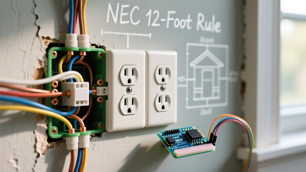
Secure the receptacle using the provided 6-32 mounting screws. Ensure the strap sits flush against the drywall or plaster ring. If the box is recessed more than 1/4 inch from the finished wall surface, NEC 314.20 requires the use of plastic or metal box extenders to close the gap and prevent fire from entering the wall cavity.
The Live Test
- Remove your LOTO device and restore power at the breaker panel.
- Plug the Gardner Bender GFI-3501 receptacle tester into the top outlet, then the bottom.
- Verify the LED sequence indicates 'Correct' (typically two amber lights on). If the tester indicates 'Open Ground', 'Reverse Polarity', or 'Hot/Neu Reverse', immediately cut power and re-inspect your terminal connections.
Advanced Edge Cases for Beginners
Not every replacement goes perfectly. Be prepared for these common residential anomalies:
- Short/Hot Wires: If the existing wires are too short to strip and loop safely (less than 3 inches protruding from the cable jacket), you must extend them. Use a wire nut and a 6-inch piece of matching gauge THHN or NM-B solid copper wire to create a pigtail extension.
- Crumbly Insulation: In homes built before 1970, the rubber or cloth insulation on the wires may flake off when bent. If the insulation falls back past the wire nut, wrap the exposed copper tightly with high-quality 3M Super 33+ vinyl electrical tape or apply heat-shrink tubing to restore the dielectric barrier.
- Missing Tamper-Resistant (TR) Markings: Per NEC 406.4(D), all 15A and 20A receptacles in dwelling units must be Tamper-Resistant. Ensure your replacement receptacle has 'TR' stamped on the face. The internal shutters prevent children from inserting foreign objects into the slots.
By adhering to these precise measurements, utilizing Spec-Grade components like the Leviton 5248-W, and respecting the torque requirements of the modern NEC, your newly replaced electrical outlet will provide decades of safe, arc-free service.