
Diagnosing Flawed Electrical Outlet and Switch Installation
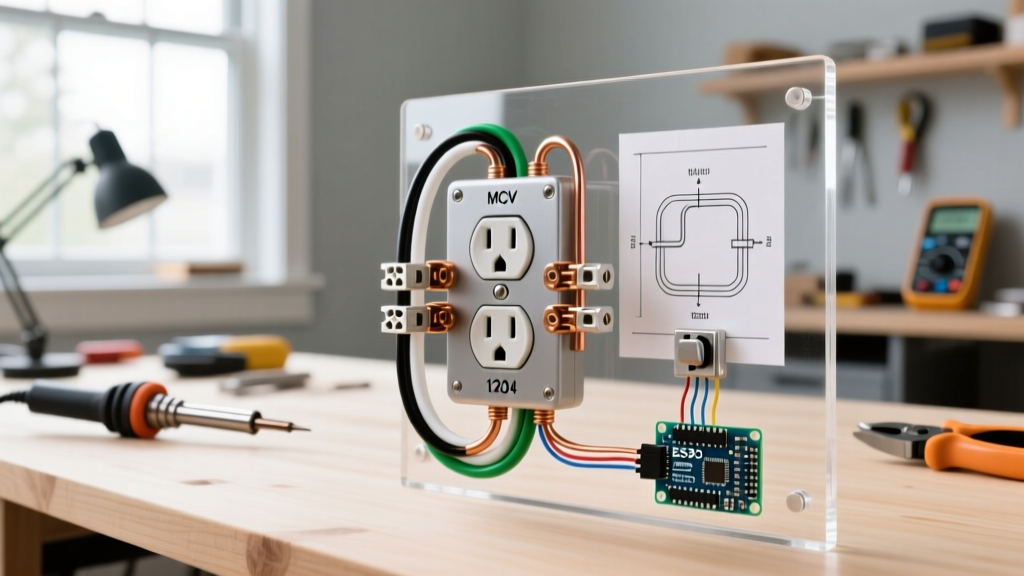
A botched electrical outlet and switch installation is rarely just a minor inconvenience; it is a latent fire hazard. According to the U.S. Consumer Product Safety Commission (CPSC), electrical receptacles and faulty wiring are responsible for thousands of residential fires annually. Whether you are auditing a recent DIY project, troubleshooting a newly renovated room, or taking over a property with questionable handyman work, systematic diagnosis is mandatory. Guessing based on wire colors is a recipe for disaster, especially in older homes where previous installers ignored standard color-coding conventions.
In this guide, we will bypass basic 'check the breaker' advice and dive deep into the multimeter diagnostics, failure modes, and code-compliant corrections required to fix the most complex installation errors found in modern residential wiring.
Phase 1: The 'Lost Neutral' and Phantom Voltage
One of the most common symptoms of a failed electrical outlet and switch installation is a receptacle that appears completely dead, yet a non-contact voltage tester (NCVT) like the Klein Tools NCVT-3 ($35) beeps wildly near the faceplate. This 'phantom voltage' almost always points to an open or 'lost' neutral upstream.
Step-by-Step Lost Neutral Diagnosis
- Test Hot-to-Ground: Set your True-RMS multimeter (such as the Fluke 117, approx. $200) to AC Voltage. Place the red probe on the shorter (hot) slot and the black probe on the grounding hole. A reading of ~120V confirms the hot feed is intact.
- Test Hot-to-Neutral: Move the black probe to the longer (neutral) slot. If the reading drops to 0V (or a erratic low voltage like 12V-40V), the neutral path is broken.
- Inspect Upstream Daisy-Chains: In standard 15-amp and 20-amp branch circuits, outlets are wired in parallel via pigtails or feed-through terminals. The failure is rarely at the dead outlet itself; it is usually at the previous working outlet in the daisy-chain.
Expert Insight: The Backstab Failure Mode
Over 70% of lost neutrals in amateur installations stem from the use of 'backstab' (push-in) connectors on the back of standard 15A receptacles. These spring-loaded clips grip 14 AWG solid copper wire poorly. Under thermal cycling (heating and cooling as loads are applied), the wire oxidizes and eventually slips out of the clip. Always use the side-screw terminals with a proper J-hook, or use wire nuts with pigtails for feed-through connections.
Phase 2: Switched Receptacle (Half-Hot) Tab Failures
In living rooms and bedrooms, building codes often require a switched receptacle to satisfy lighting requirements if no overhead fixture is present. A common installation error occurs when the installer fails to manipulate the break-off tabs on the duplex receptacle, resulting in either a completely dead switched half or a receptacle that is constantly hot regardless of the wall switch position.
Correcting the Brass Fin Error
- Both Halves Always Hot: The installer wired the switch loop to the brass (hot) terminal but forgot to snap off the connecting brass fin between the top and bottom receptacles. Power is bypassing the switch entirely.
- Both Halves Switched: The installer snapped off the silver (neutral) tab instead of the brass tab. This is a severe code violation and a shock hazard, as it switches the neutral return path while leaving the receptacle constantly energized.
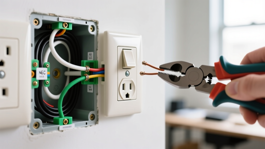
- The Fix: Remove the receptacle. Identify the brass (hot) side. Use a pair of needle-nose pliers to snap the brass fin connecting the two brass screws. Ensure the silver (neutral) fin remains completely intact. Connect the always-hot feed to one brass screw, and the switch-loop return to the other brass screw.
Phase 3: GFCI Line/Load Reversal and Nuisance Tripping
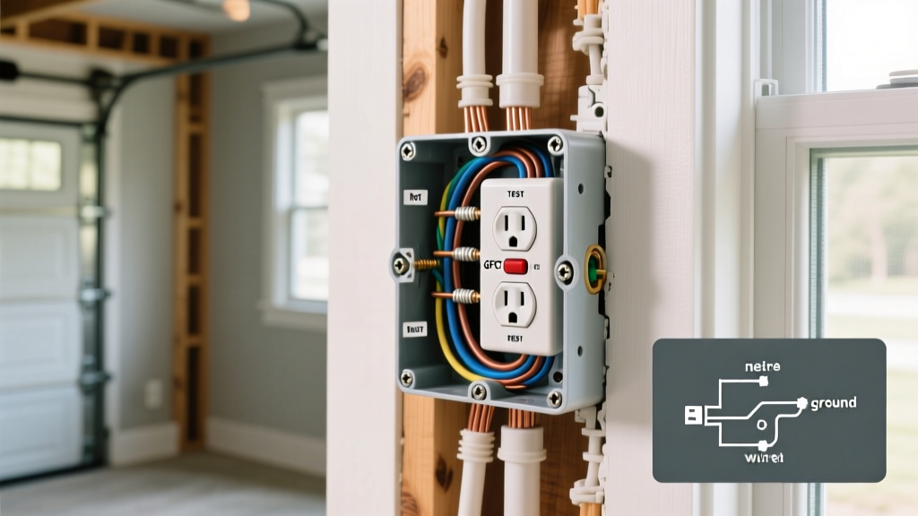
Modern electrical outlet and switch installation heavily involves Ground Fault Circuit Interrupter (GFCI) devices, mandated by the National Electrical Code (NEC / NFPA 70) for kitchens, bathrooms, garages, and outdoor areas. A frequent post-installation complaint is a GFCI that either will not reset or trips immediately when a load is applied.
Diagnosing Line vs. Load Confusion
Standard GFCI receptacles, such as the Leviton SmartlockPro T5999-W ($22), feature two distinct sets of terminals: LINE (incoming power) and LOAD (downstream protection).
- The 'Won't Reset' Symptom: If the incoming power is wired to the LOAD terminals, the internal sensing circuitry will not energize the reset solenoid. The button will simply push in and pop back out. Use a multimeter to identify the live feed wires, disconnect them, and attach them strictly to the LINE terminals.
- The 'Shared Neutral' Trip: If the GFCI trips the moment you turn on a light or appliance on a downstream circuit, the installer likely shared a neutral wire between two different hot phases or a standard circuit and an AFCI/GFCI circuit. GFCIs monitor the current differential between the hot and neutral. If return current travels back via a shared neutral outside the GFCI's sensing toroid, the device reads this as a ground fault and trips. The only fix is to pull a dedicated neutral wire for the downstream load.
Diagnostic Matrix: Multimeter Readings & Fault Identification
| Symptom | Hot-to-Neutral (VAC) | Hot-to-Ground (VAC) | Neutral-to-Ground (VAC) | Probable Installation Fault |
|---|---|---|---|---|
| Dead Outlet, NCVT Beeps | 0V - 40V | ~120V | ~120V | Open/Lost Neutral upstream |
| Reversed Polarity | ~120V | 0V | ~120V | Hot and Neutral swapped at terminals |
| False / Bootleg Ground | ~120V | ~120V | 0V | Neutral jumpered to Ground screw (Severe Hazard) |
| High Resistance Joint | 105V - 115V (under load) | ~120V | 0V | Loose wire nut or degraded backstab connection |
Phase 4: 3-Way Switch Traveler Mapping Errors
When an electrical outlet and switch installation involves 3-way switches (controlling a load from two locations), miswired traveler wires result in switches that only work in specific toggle combinations. This happens when the installer fails to identify the 'Common' terminal.
Mapping the Terminals Without Relying on Wire Colors
Never trust the colors of the wires in a 3-way switch box. Previous installers frequently use whatever wire was left over in their pouch. Instead, rely on the physical geometry of the switch itself (e.g., a standard Leviton 5603 or a Lutron Maestro MACL-153M dimmer).
- Identify the Common: The common terminal is almost always a darker-colored screw (black or dark brass) and is physically isolated from the other two screws, which are usually positioned on the same side of the strap or marked as 'Travelers'.
- Continuity Testing: With the breaker OFF, use your multimeter's continuity setting. Place one probe on the Common screw and the other on a Traveler screw. Flip the toggle. The continuity should shift from one traveler to the other.
- The Fix: The wire connected to the Common screw on Switch A must be the continuous hot feed from the panel. The wire connected to the Common screw on Switch B must be the switch leg going down to the light fixture. The remaining two wires in each box are the travelers, which must connect to the traveler screws on both switches. If the fixture still fails to operate correctly, the installer likely mixed a traveler with the switch leg at the ceiling junction box.
Safety Protocols and Code Compliance
Troubleshooting live circuits requires strict adherence to safety protocols. The Occupational Safety and Health Administration (OSHA) mandates the use of appropriately rated personal protective equipment (PPE) and Category III (CAT III) or Category IV (CAT IV) rated testing equipment when diagnosing energized residential panels and receptacles.
Furthermore, as of the latest NEC cycles adopted into local jurisdictions through 2026, virtually all 120V, 15A, and 20A receptacles in living spaces require Arc-Fault Circuit Interrupter (AFCI) protection, while wet locations demand GFCI protection. If your troubleshooting reveals that a standard breaker is feeding a bedroom circuit without AFCI protection, or a kitchen counter circuit lacks GFCI, the installation is fundamentally non-compliant. Correcting these errors requires upgrading the breaker panel with combination-type AFCI/GFCI breakers (such as the Eaton BR120AFIC, approx. $65) or installing dual-function receptacles at the first outlet in the branch circuit.
Final Verification
Once all physical wiring faults are corrected, do not rely solely on a visual inspection. Use a commercial-grade receptacle tester (like the Gardner Bender GRT-930) to verify correct wiring sequence, and perform a final voltage drop test under a simulated 10A load to ensure all terminal connections are tight and free of thermal degradation risks. Proper diagnosis transforms a hazardous wall box into a safe, code-compliant termination point.