
The 2026 Safety Standard: Why Upgrading Matters
Learning how to replace an electrical outlet is one of the most foundational and rewarding skills a homeowner or DIY enthusiast can acquire. Whether you are dealing with a cracked faceplate, a loose plug that falls out of the socket, or a discolored receptacle showing signs of thermal damage, swapping out a standard 120V duplex receptacle is a straightforward process when approached with methodical precision. According to the National Fire Protection Association (NFPA), electrical failures or malfunctions are a leading cause of home fires, often stemming from degraded receptacle contacts or improper wiring techniques. In 2026, the National Electrical Code (NEC) continues to mandate Tamper-Resistant (TR) receptacles in nearly all indoor residential spaces, making this upgrade not just a cosmetic fix, but a critical safety enhancement.
CRITICAL SAFETY WARNING: Never attempt to work on an energized circuit. Electrocution is fatal. Always verify the power is off using a reliable non-contact voltage tester before touching any bare wires or terminal screws.
Anatomy of a 15A vs. 20A Duplex Receptacle
Before unscrewing your wall plate, you must understand what you are working with. Standard residential outlets come in two primary amperage ratings:
- 15-Amp Receptacles (NEMA 1-15R / 5-15R): Wired with 14 AWG copper wire, protected by a 15A breaker. These are standard in bedrooms, living rooms, and hallways.
- 20-Amp Receptacles (NEMA 5-20R): Wired with 12 AWG copper wire, protected by a 20A breaker. These feature a distinct T-shaped neutral slot and are required in kitchens, bathrooms, and garages.
On the brass (gold) side of the outlet, you will find the hot terminal screws, which connect to the black (or red) wire. On the silver side, you will find the neutral terminal screws, connecting to the white wire. The green screw at the bottom is for the ground wire (bare copper or green). Between the two brass screws and the two silver screws, you will notice a small metal tab called the 'break-off fin'. This fin allows both top and bottom outlets to share the same circuit. If your outlet is 'split-wired' (where one half is controlled by a wall switch and the other is always hot), this fin will be broken off.
Essential Tool Kit & Material Sourcing
Using the correct tools prevents wire damage and ensures a secure mechanical connection. Below is a curated list of professional-grade tools and materials recommended for a 2026 DIY installation.
| Tool / Material | Recommended Model | Est. Cost (2026) | Purpose |
|---|---|---|---|
| Non-Contact Voltage Tester | Fluke 1AC-II VoltAlert | $28.00 - $35.00 | Verify circuit is de-energized |
| Wire Strippers | Klein Tools 11055 | $25.00 - $32.00 | Strip 14/12 AWG without nicking copper |
| Insulated Screwdriver | Wiha 32095 SoftFinish | $12.00 - $18.00 | Terminal connections with shock protection |
| 15A TR Receptacle | Leviton 5262-SW | $1.50 - $2.50 | Standard indoor tamper-resistant replacement |
| 20A TR Receptacle | Hubbell 5266-TR | $4.50 - $6.00 | Kitchen/Bath heavy-duty replacement |
Step-by-Step: How to Replace an Electrical Outlet
Phase 1: De-energize and Verify
Locate your main electrical panel and switch off the breaker controlling the room you are working in. If your breakers are not labeled, plug a lamp into the outlet and turn breakers off until the lamp dies. Once off, remove the outlet cover plate. Insert your Fluke VoltAlert into the slots and touch it to the side of the receptacle. The tool must remain silent and unlit. For absolute certainty, remove the outlet mounting screws, pull the receptacle out, and test the bare wires directly.
Phase 2: Extraction and Forensic Inspection
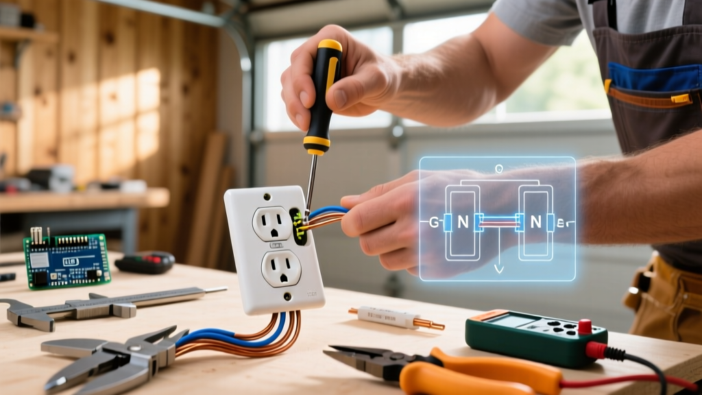
Unscrew the top and bottom mounting screws and gently pull the outlet from the junction box. Stop and take a photograph of the existing wiring. This is your ultimate reference. Inspect the wires and the plastic housing of the old outlet. If you see melted plastic, scorch marks, or brittle, blackened wire insulation, you are dealing with a high-resistance connection or historical overload. Damaged insulation must be cut back to clean copper; if the wires are too short after cutting, you will need to pigtail them using wire nuts and 6-inch jumper wires.
Phase 3: Wire Preparation (The 5/8-Inch Rule)
Most modern Leviton and Hubbell receptacles feature a 'strip gauge' molded into the back of the plastic housing. This is typically 5/8 of an inch. Using your Klein wire strippers, cut off any old, oxidized, or nicked ends of the copper wire. Strip exactly 5/8 inch of insulation. Stripping too little leaves exposed insulation under the screw head, causing a high-resistance joint. Stripping too much leaves bare, live copper exposed outside the terminal, creating a severe shock and short-circuit hazard.
Phase 4: Termination Methods (Side-Wire vs. Back-Wire)
There are three ways to connect wires to a receptacle, but only two are acceptable for a safe, long-lasting installation:
- Push-In Backstab (AVOID): Older and cheaper receptacles feature small holes on the back where you simply push the stripped wire in. The Consumer Product Safety Commission (CPSC) and most master electricians advise against these. They rely on a tiny spring-metal clip that loosens over time due to thermal expansion and contraction, leading to arcing and fires.
- Screw-Clamp Back-Wiring (PREFERRED): Higher-end 2026 receptacles feature a clamp plate under the terminal screw. You insert the straight, stripped wire into the back hole, then tighten the screw, which clamps a brass plate down onto the wire. This offers maximum surface area contact and is incredibly secure.
- Side-Wiring / Shepherd's Hook (TRADITIONAL): If using the side screws, use needle-nose pliers to bend the stripped wire into a tight 'U' shape (shepherd's hook). Loop it around the screw clockwise. When you tighten the screw (which turns clockwise), it will pull the loop tighter around the shaft. If you loop it counter-clockwise, tightening the screw will push the wire out.
Connect the bare/green ground wire to the green screw first. Next, connect the white neutral wire(s) to the silver screws. Finally, connect the black hot wire(s) to the brass screws.
Phase 5: Box Dressing and Final Torque
Fold the wires neatly into the back of the junction box. A common beginner mistake is shoving the wires in haphazardly, which can pinch the ground wire against the hot terminal and trip the breaker immediately. Create a smooth 'Z' fold. Push the receptacle flush against the drywall and secure it with the provided mounting screws. While residential DIYers rarely use torque screwdrivers, the NEC emphasizes tightening terminal screws to the manufacturer's specifications (usually around 14 in-lbs). Ensure the outlet is snug, but do not overtighten to the point of cracking the plastic yoke.
Edge Cases: Split-Wired and Multi-Wire Branch Circuits
If you pull out your old outlet and see two black wires and two white wires connected to it, or a red wire and a black wire on the brass screws, you have a complex setup.
- Split-Wired Outlets: Common in living rooms, the top outlet is controlled by a wall switch, while the bottom is always on. The brass fin must be broken off using pliers before installing the new receptacle. If you forget this step, turning on the wall switch will create a dead short between the always-hot and switched-hot legs, resulting in a loud pop and a tripped breaker.
- Multi-Wire Branch Circuits (MWBC): If you see a red wire and a black wire on the hot side, they likely come from two different breaker poles sharing a single neutral wire. WARNING: You must turn off BOTH breakers (usually tied together with a handle tie) before working on this. The U.S. Department of Energy highlights MWBCs as a specific hazard if the shared neutral is disconnected while one leg is still energized.
Troubleshooting Common Post-Installation Failures
If you restore power and encounter issues, use this diagnostic matrix to identify the failure mode:
| Symptom | Probable Cause | Corrective Action |
|---|---|---|
| Breaker trips instantly upon reset | Hot wire touching ground/neutral, or broken fin missing on split-wired outlet. | Re-inspect box for pinched wires; verify fin removal if red/black wires are present. |
| Outlet works, but downstream GFCI trips | Line and Load wires reversed on a GFCI-protected circuit. | Identify the incoming power source (Line) and connect it to the LINE terminals only. |
| Receptacle sits crooked or loose | Uneven drywall cutout or missing shims. | Install plastic outlet shims (e.g., Leviton R52-00RSP) behind the mounting ears. |
| Plugs feel loose and fall out | Internal brass contacts are fatigued (if reusing old outlet) or cheap manufacturing. | Always replace with a commercial-grade or high-quality residential TR receptacle. |
Authoritative References and Further Reading
Electrical work requires adherence to local and national codes. Always consult your local Authority Having Jurisdiction (AHJ) regarding permits for electrical replacements in your municipality. For ongoing safety guidelines, refer to the NFPA Electrical Safety Portal and the CPSC Electrical Safety Center. By following these precise, methodical steps, you ensure your home's electrical infrastructure remains safe, code-compliant, and reliable for decades to come.