
Why the 50-Amp NEMA 14-50 is the Modern Standard
Installing a dedicated electric range outlet is one of the most critical high-voltage projects in a residential kitchen. Modern electric ranges, dual-fuel ovens, and heavy-duty induction cooktops demand significant power, typically requiring a 240-volt, 50-amp circuit. Since the 1996 National Electrical Code (NEC) update, the industry has strictly transitioned away from older 3-prong setups to the 4-prong NEMA 14-50R receptacle. This configuration separates the neutral and ground paths, eliminating the risk of stray voltage on the appliance chassis.
In this comprehensive guide, we will walk through the exact step-by-step installation of a 50-amp electric range outlet, integrating the latest 2026 NEC compliance standards, precise torque specifications, and advanced troubleshooting techniques used by master electricians.
Pre-Installation: Materials, Tools, and NEC Compliance
Before touching the service panel, you must gather the correct materials. Undersized wire or improper enclosures are leading causes of thermal failures in high-amperage circuits.
Essential Components
- Circuit Breaker: 50-Amp double-pole breaker (e.g., Square D HOM250 or Eaton BR250, depending on your panel brand). Cost: $15–$25.
- Conductor Cable: 6 AWG copper, 4-conductor (6/3 NM-B Romex for indoor dry locations, or 6 AWG THHN/THWN in conduit). Cost: ~$2.50–$3.50 per foot.
- Receptacle: NEMA 14-50R, 50-Amp, 125/250V (e.g., Leviton 278-S00 or Hubbell 9450A). Cost: $12–$20.
- Electrical Box: A standard single-gang box is too small for 6 AWG wire. You must use a deep 2-gang box, a 4-inch square box with a single-gang plaster ring, or a specialized deep masonry box (minimum 42 cubic inches to satisfy NEC Chapter 9 box fill calculations).
The NEC Torque Requirement (110.14(D))
One of the most vital updates in recent NEC cycles (which remains strictly enforced in 2026) is Section 110.14(D). This code mandates the use of a calibrated torque screwdriver for all terminal connections rated 100 amps or less. Hand-tightening a 50-amp receptacle is no longer code-compliant and is a primary cause of arc faults. Most NEMA 14-50R terminals require between 14 and 20 inch-pounds of torque. Always verify the exact specification printed on the back of the receptacle.
Step-by-Step Installation Guide
Step 1: Breaker Installation at the Panel
- De-energize the Panel: Turn off the main service disconnect. Verify the bus bars are dead using a non-contact voltage tester and a digital multimeter.
- Seat the Breaker: Snap the 50-amp double-pole breaker firmly onto the bus bar stabs. Ensure it seats evenly on both phases to draw 240V.
- Terminate the Ground and Neutral: Connect the bare copper ground wire to the equipment grounding bus bar. Connect the white neutral wire to the isolated neutral bus bar. Never mix grounds and neutrals on a subpanel, though they are bonded at the main service disconnect.
- Connect the Hots: Strip exactly 5/8 inch of insulation from the black and red conductors. Insert them into the breaker terminals and torque to the manufacturer’s specification (typically 35-45 in-lbs for 6 AWG copper on standard Square D breakers).
Step 2: Routing the 6 AWG Feeder Cable
Running 6/3 NM-B cable requires attention to physical protection and bending radius. Because the wire is thick and stiff, sharp bends can damage the internal insulation or compromise the paper wrapping.
- Securing the Cable: Per NEC 334.30, NM-B cable must be secured within 12 inches of the electrical box and at intervals not exceeding 4.5 feet.
- Drilling Holes: When drilling through wall studs, maintain a minimum 1.25-inch setback from the edge of the stud to prevent drywall screws from piercing the cable later. Use nail plates if you cannot achieve this setback.
- Entering the Box: Use a proper Romex connector (cable clamp) to secure the 6/3 wire to the electrical box. Leave at least 8 inches of working length inside the box, but do not leave excessive slack that violates box fill capacity.
Step 3: Terminating the NEMA 14-50R Receptacle
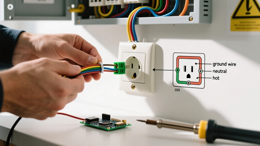
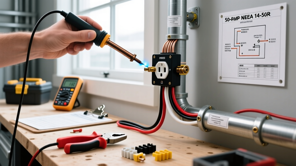
Proper termination at the electric range outlet is where most DIY errors occur. The NEMA 14-50R features four distinct terminals:
- X (Left Brass): Black wire (Hot 1 - 120V)
- Y (Right Brass): Red wire (Hot 2 - 120V)
- W (Silver): White wire (Neutral - 120V return)
- G (Green): Bare or Green wire (Equipment Ground)
Strip the wire insulation to the exact depth gauge molded into the back of the receptacle (usually 5/8 inch). Ensure no bare copper is exposed outside the terminal, and no insulation is pushed inside the terminal clamp. Apply your calibrated torque screwdriver to tighten the screws to the specified inch-pounds. Finally, mount the receptacle to the box using the provided 6-32 or 8-32 machine screws, ensuring the yoke sits flush against the drywall or tile.
3-Prong vs. 4-Prong Configurations
Homeowners renovating older kitchens often ask if they can reuse an existing 3-prong outlet. According to the National Fire Protection Association (NFPA), new installations must exclusively use the 4-prong setup. The table below highlights the critical differences.
| Feature | NEMA 10-50 (Old 3-Prong) | NEMA 14-50 (Modern 4-Prong) |
|---|---|---|
| Conductors | 2 Hots, 1 Combined Neutral/Ground | 2 Hots, 1 Neutral, 1 Dedicated Ground |
| Safety Risk | High: Chassis can become energized if neutral fails | Low: Ground fault path is entirely separate from current-carrying neutral |
| NEC Status | Grandfathered for existing installs only; banned for new runs | Mandatory for all new residential and commercial installations |
| Cord Set | 3-wire range cord (bonding strap required on appliance) | 4-wire range cord (bonding strap must be removed on appliance) |
Testing and Commissioning
Before plugging in your $2,000 induction range, you must verify the circuit's electrical characteristics. Turn the main breaker back on, followed by the 50-amp double-pole breaker.
Set your digital multimeter to AC Voltage (V~) and perform the following checks at the receptacle slots:
- Hot to Hot (X to Y): Should read exactly 240V (±5%).
- Hot 1 to Neutral (X to W): Should read 120V.
- Hot 2 to Neutral (Y to W): Should read 120V.
- Hot to Ground (X to G, Y to G): Should read 120V.
- Neutral to Ground (W to G): Should read 0V (or a negligible phantom voltage under 1V).
If you read 240V between Neutral and Ground, you have a severe wiring fault—likely a crossed neutral and hot wire at the panel. Shut off the breaker immediately and re-inspect your terminations.
Advanced Troubleshooting & Failure Modes
Even with a perfect installation, specific failure modes can plague an electric range circuit. Understanding these edge cases separates professional electricians from amateurs.
The 'Loose Neutral' Catastrophe
Modern electric ranges use 240V for the heating elements but rely on 120V for the control boards, digital clocks, and Wi-Fi smart modules. If the neutral terminal at the receptacle is loose (often due to failing to use a torque screwdriver), the 120V return path is compromised. This creates a floating neutral scenario where the voltage on the 120V control board can swing wildly from 0V up to 240V, depending on the resistance of the heating elements. This voltage spike will instantly fry the appliance's main PCB. Always torque the silver neutral terminal to spec.
Inrush Current Nuisance Tripping
Some modern smart ranges with heavy capacitive power supplies can experience high inrush currents when first plugged in or powered on. If your 50-amp breaker trips immediately upon energizing the range, but tests fine on a multimeter, you may be experiencing magnetic trip nuisance tripping. Ensure you are using a standard thermal-magnetic breaker and not a GFCI or AFCI breaker, as NEC 210.19 does not typically require GFCI protection for standard freestanding electric ranges (though local 2026 amendments may vary for specific jurisdictions). For further safety guidelines regarding high-voltage appliance circuits, refer to the U.S. Consumer Product Safety Commission (CPSC) electrical safety resources.
Thermal Scanning
After running the range's self-cleaning cycle (which draws maximum continuous amperage for 2-4 hours), use an infrared thermal camera to scan the receptacle face and the panel breaker. Temperatures exceeding 140°F (60°C) at the terminal connections indicate high resistance, requiring immediate de-energization and re-termination.