
Why Outdoor Outlets Fail and the Modern Safety Standard
Outdoor electrical receptacles endure brutal conditions, including UV radiation, driving rain, and extreme temperature fluctuations. Over time, standard covers crack, gaskets degrade, and moisture infiltrates the electrical box, leading to corrosion, nuisance tripping, or severe shock hazards. If your exterior receptacle is cracked, discolored, or frequently trips, it is time for a replacement.
Replacing an outdoor outlet is a highly manageable DIY project, provided you adhere to modern electrical codes and use the correct weather-resistant components. According to the National Fire Protection Association (NFPA 70), all outdoor 15-amp and 20-amp, 125-volt and 250-volt receptacles must be protected by a Ground Fault Circuit Interrupter (GFCI) and covered with an "in-use" weatherproof enclosure. This guide will walk you through the exact steps, tools, and torque specifications required to replace an outdoor electrical outlet safely and to code.
Essential Tools and Materials Checklist
Do not attempt this project with substandard materials. Outdoor components must carry a "WR" (Weather-Resistant) and "TR" (Tamper-Resistant) rating. Expect to spend roughly $65 to $85 on high-quality parts and specialized tools.
- Receptacle: Leviton 8599-W (20-Amp, TR, WR, GFCI) — Approx. $24.00
- Cover: TayMac MX850W Extra-Duty In-Use Weatherproof Cover — Approx. $19.00
- Sealant: GE Silicone II 100% Waterproof (Clear) — Approx. $7.00
- Voltage Tester: Klein Tools NCVT-3 Non-Contact Voltage Tester — Approx. $28.00
- Wire Strippers: Klein Tools 11063W (10-14 AWG) — Approx. $25.00
- Torque Screwdriver: CDI 401SM (10-50 in-lbs) or Klein 69020 — Approx. $45.00 (Crucial for code compliance)
Understanding NEC Code Requirements for Exterior Outlets
Before touching a screwdriver, you must understand the rules governing outdoor wiring. The Electrical Safety Foundation International (ESFI) emphasizes that GFCIs are non-negotiable for outdoor circuits due to the high risk of ground faults caused by moisture. Furthermore, the National Electrical Code (NEC) Article 406.9(B)(1) mandates that receptacles installed in damp or wet locations must be enclosed in a weatherproof enclosure that provides protection even when a cord is plugged in (commonly known as an "in-use" or "bubble" cover). Finally, NEC Article 110.14(D) requires that terminal connections be torqued to the manufacturer's specified values to prevent thermal expansion loosening over time.
Step-by-Step Installation Tutorial
Step 1: Kill the Power and Verify
Navigate to your main electrical panel and switch off the breaker controlling the outdoor circuit. If your panel is poorly labeled, plug a lamp or radio into the outdoor outlet before flipping breakers to identify the correct one. Once off, use your Klein NCVT-3 tester on the outlet slots and the surrounding box. Never assume a breaker label is accurate; always verify zero voltage before proceeding.
Step 2: Remove the Old Cover and Receptacle
Unscrew the existing weatherproof cover and set the hardware aside. Next, remove the two long machine screws securing the receptacle to the electrical box. Gently pull the receptacle out. Take a photo of the existing wiring configuration. Note whether the wires are connected to the "LINE" or "LOAD" terminals. If there is only one set of wires (one black, one white, one bare copper), they must connect to the LINE terminals.
Step 3: Inspect the Box and Prep the Wires
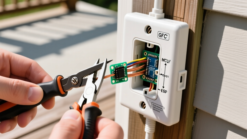
Examine the interior of the electrical box. If it is a cast aluminum box, look for white, powdery oxidation. If it is PVC, check for cracks. Use a wire brush to clean any minor corrosion. Next, inspect the copper conductors. If the ends are blackened or heavily corroded, snip them back. Using your Klein 11063W strippers, strip exactly 3/4-inch of insulation from the black (hot) and white (neutral) wires. Do not nick the copper conductor, as this creates a weak point that can snap under torque.
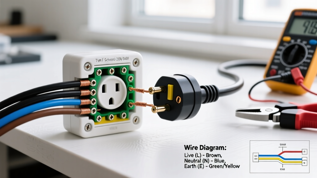
Step 4: Wire the New WR GFCI Receptacle
This is where most beginners make critical errors. The Leviton 8599-W features yellow tape covering the LOAD terminals and black tape covering the LINE terminals. For a single-cable setup, remove ONLY the black tape.
- Ground: Loop the bare copper wire clockwise around the green ground screw.
- Neutral: Insert the stripped white wire into the silver LINE terminal hole. Ensure no bare copper is visible outside the terminal block.
- Hot: Insert the stripped black wire into the brass LINE terminal hole.
Pro Tip: Use your torque screwdriver set to 14 in-lbs (the standard specification for 12 AWG copper on Leviton GFCIs). A proper click ensures the connection will not loosen due to seasonal thermal expansion, preventing dangerous arcing.
Step 5: Install the In-Use Weatherproof Cover
Carefully fold the wires back into the box, ensuring the ground wire does not touch the brass or silver terminals. Attach the foam gasket provided with the TayMac MX850W cover to the receptacle face. Mount the cover using the provided corrosion-resistant screws. Apply a continuous bead of GE Silicone II along the top and both sides of the cover where it meets the siding or masonry. Do not caulk the bottom edge. Leaving the bottom unsealed creates a weep hole, allowing any internal condensation to drain out rather than pooling inside the enclosure.
Comparing Weatherproof Cover Types
Choosing the right enclosure is just as important as the receptacle itself. Below is a comparison of the two primary in-use cover designs available on the market.
| Feature | Extra-Deep Bubble Cover (e.g., TayMac MX850W) | Flat / Slanted In-Use Cover |
|---|---|---|
| Clearance for Plugs | Excellent (Accommodates large power tool plugs and smart home adapters) | Poor to Fair (Often forces large plugs against the plastic, breaking the seal) |
| Aesthetics | Bulky; protrudes 3 to 4 inches from the wall | Sleek; low-profile design blends better with siding |
| Weather Deflection | Good, but hinges can collect debris over time | Excellent; slanted top sheds snow and rain efficiently |
| Best Use Case | Patios, workshops, and holiday lighting setups | Landscaping lighting transformers, low-profile sprinkler timers |
Troubleshooting Common Failure Modes
Even with a flawless installation, outdoor circuits can present unique challenges. Here is how to diagnose the most common post-installation issues:
- Nuisance Tripping During Rain: If the GFCI trips only during heavy storms, moisture is likely bypassing the cover gasket. Check if the foam gasket is compressed evenly. If the electrical box is mounted on uneven stucco or wood, the gasket will gap. Solution: Apply a thicker bead of silicone behind the gasket or use a surface-mount spacer ring to create a flat mounting plane.
- GFCI Will Not Reset: Ensure you have power at the LINE terminals. If you accidentally wired the incoming power to the LOAD terminals, the internal GFCI circuitry will not energize, and the reset button will remain dead. Swap the wires to the LINE side.
- Downstream Outlets Are Dead: If you wired the LOAD terminals to protect a downstream receptacle (like a garage or patio string), a loose neutral on the load side will kill power to the entire chain. Re-torque the load neutral to 14 in-lbs.
Final Safety Verification
Once the silicone has cured (typically 24 hours for a full waterproof seal), plug in a GFCI receptacle tester (like the Gardner Bender GFI-3501). Press the test button on the tester to ensure the outlet trips correctly, then press the reset button on the receptacle itself. By following these precise measurements, torque specifications, and sealing techniques, your new outdoor electrical outlet will provide safe, reliable power for years to come, fully compliant with modern safety standards.