
Mastering Electrical Wiring Light Switch Diagrams for Safe Installation
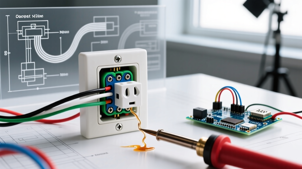
Interpreting electrical wiring light switch diagrams is the foundational skill that separates a safe, code-compliant installation from a dangerous fire hazard. Whether you are upgrading a standard toggle to a smart dimmer or wiring a complex 4-way circuit, the diagram is your logical roadmap. Unlike physical photographs, schematic diagrams abstract the physical layout to reveal the electrical path: line, load, neutral, and ground.
In this comprehensive guide, we will decode standard switch schematics, outline the exact tools required for modern terminations, and provide step-by-step installation procedures for single-pole and 3-way configurations, keeping current National Electrical Code (NEC) standards in mind.
Decoding the Schematic: Standard Diagram Symbols
Before touching a wire stripper, you must understand the visual language of electrical schematics. Manufacturers like Leviton, Lutron, and Eaton use standardized symbols in their installation sheets. Misinterpreting a traveler wire as a line wire is the most common cause of 3-way switch failure.
| Diagram Symbol / Label | Wire Color (Standard US) | Function & Expert Context |
|---|---|---|
| LINE (Hot) | Black (or Red) | Brings unswitched 120V power from the breaker panel to the switch. |
| LOAD | Black (or Red) | Carries switched power from the switch to the light fixture. |
| NEUTRAL | White | Completes the circuit back to the panel. Required for smart switches and dimmers with LED compatibility. |
| GROUND | Bare Copper / Green | Safety path for fault currents. Must be bonded to the metal box and switch yoke. |
| TRAVELER | Red / Black (in 3-wire cable) | Interconnects two 3-way switches. Polarity between travelers does not matter. |
The Professional Tool Kit for Switch Wiring
Skip the $5 multi-tool from the hardware store bin. Proper terminations require specific tools to prevent loose connections, which cause arcing and thermal failure. According to the National Fire Protection Association (NFPA), loose terminations are a leading cause of residential electrical fires.
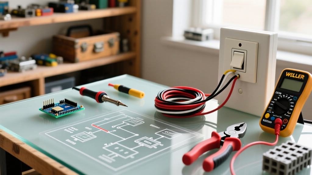
- Voltage Tester: Fluke 1AC-II VoltAlert ($30). Non-contact, CAT IV rated. Always verify on a known live source before and after testing the target wire.
- Wire Strippers: Klein Tools 11063W ($25). Specifically gauged for 14 AWG and 12 AWG solid copper to prevent nicking the conductor, which creates a weak point that snaps under screw torque.
- Connectors: Wago 221 Lever-Nuts ($0.50 each). Superior to twist-on wire nuts for pigtailing. They provide a verifiable, gas-tight connection and allow for easy circuit modifications later.
- Torque Screwdriver: While NEC 110.14(D) primarily targets breaker terminations, premium smart switches (like the Lutron Caseta) specify exact torque values (often 14 in-lbs) for their terminal screws.
Step-by-Step: Single-Pole Switch Installation
A single-pole switch controls a light from one location. The diagram for this setup is straightforward: the hot line enters the switch, and the load exits to the fixture. The neutral wires bypass the switch entirely, spliced together in the back of the box.
Step 1: Power Verification and Box Prep
Turn off the breaker. Use your Fluke 1AC-II to verify zero voltage at the switch terminals. Remove the old switch. If the box is crowded with 12/2 Romex, use Wago 221-413 connectors to create a neat pigtail for the ground wires, freeing up physical space for the new switch yoke.
Step 2: Stripping and Shaping the Wire
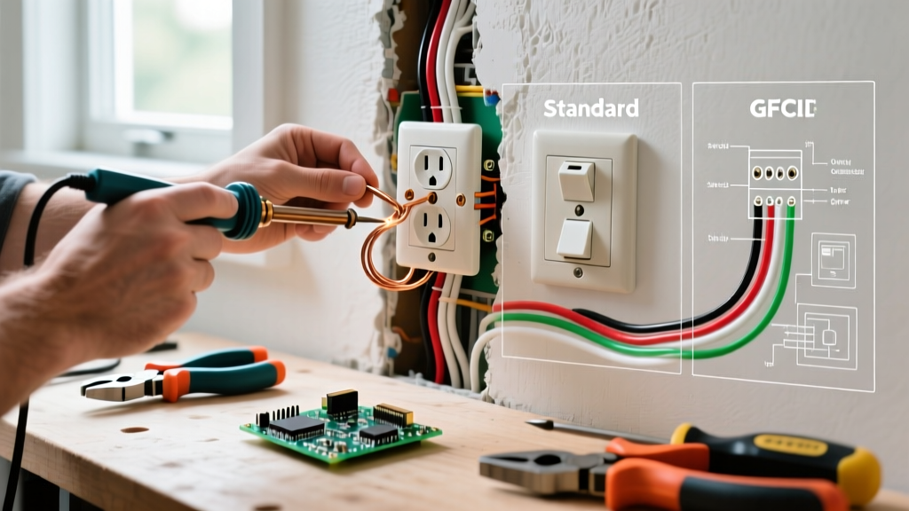
Strip exactly 3/4 inch of insulation from the black (line) and black (load) wires. Using the hole in your Klein strippers or needle-nose pliers, bend a perfect J-hook in the copper. This ensures the wire wraps completely around the terminal screw.
Step 3: Terminal Termination
Expert Warning: Never use the "backstab" push-in terminals found on cheap contractor-grade switches (e.g., standard $1.50 toggles). The internal spring grips weaken over time due to thermal cycling, leading to arcing. Always use the side-screw terminals.
Hook the line wire clockwise around the top brass screw. Hook the load wire clockwise around the bottom brass screw. Tighten to 14 in-lbs. Connect the bare ground to the green grounding screw on the switch yoke.
Step-by-Step: 3-Way Switch Installation (Decoding Travelers)
3-way diagrams confuse most DIYers because the physical wire colors in the wall rarely match the colors printed on the manufacturer's diagram. The secret is identifying the LINE, LOAD, and TRAVELERS using logic, not just color.
Step 1: Identify Line and Load
In a 3-way circuit, one switch box receives the constant hot (LINE) from the panel, and the other switch box sends the switched hot (LOAD) to the light.
Pro-Tip: If you are replacing old switches, note which wire was connected to the black (or distinctly colored) "Common" screw on the old switch. That wire is your Line (in box 1) or Load (in box 2).
Step 2: Map the Travelers
The two remaining wires in each box are the travelers. They run through the 3-conductor cable (usually red and black) connecting the two switch boxes. On your new 3-way switches, connect these two traveler wires to the two brass-colored screws. It does not matter which traveler goes to which brass screw.
Step 3: Wire the Common Screws
Connect the LINE wire to the black common screw on Switch 1. Connect the LOAD wire to the black common screw on Switch 2. Terminate all ground wires to the green screws and the metal box.
Common Wiring Mistakes and NEC Compliance
Even with a perfect diagram, physical installation errors can compromise safety. The U.S. Consumer Product Safety Commission (CPSC) emphasizes that improper switch wiring contributes to thousands of home fires annually.
1. The Switched Neutral (Bootleg Switching)
The Error: Breaking the white neutral wire to switch the light while leaving the black hot wire constantly connected to the fixture.
Why it Fails: The light turns off, but the fixture remains energized at 120V. Changing a bulb becomes a lethal shock hazard. NEC 404.2(B) strictly requires switches to interrupt the ungrounded (hot) conductor.
2. Floating Grounds in Metal Boxes
The Error: Connecting the ground wire to the switch, but failing to bond the metal electrical box itself.
The Fix: Use a green grounding clip or a 10-32 ground screw tapped into the back of the metal box. Pigtail the box ground to the switch ground using a Wago lever nut.
3. Overcrowding and Box Fill Violations
Smart switches (like the Kasa KS220M or GE Cync) are physically massive. If you are installing them in a standard 14-cubic-inch single-gang box that already holds three 14/2 cables, you are violating NEC 314.16 box fill calculations.
The Fix: Upgrade to an "old work" deep box (minimum 22 cubic inches) to accommodate the switch depth and the necessary neutral wire pigtails.
Frequently Asked Questions (FAQ)
Do I need a neutral wire for a standard light switch?
No. A standard mechanical single-pole switch only interrupts the hot wire and does not require a neutral connection. However, if you are installing a smart switch, Wi-Fi relay, or certain advanced LED dimmers, a neutral wire is mandatory to power the switch's internal electronics.
What happens if I wire a 3-way switch backward?
If you swap the line/load with the travelers, the circuit will not function correctly. The light may turn on from only one location, or it may remain on permanently regardless of switch position. Always identify the common (dark) screw before disconnecting old hardware.
Can I use 14 AWG wire on a 20-Amp breaker circuit?
Absolutely not. If your bathroom or kitchen switch is on a 20-Amp breaker, you must use 12 AWG copper wire and a switch rated for 20 Amps (e.g., Leviton 1220). Using 14 AWG on a 20A circuit is a severe fire hazard and a direct violation of NEC 240.4(D).
For further safety guidelines and best practices regarding residential electrical work, consult resources provided by the Electrical Safety Foundation International (ESFI). Always pull a local permit for electrical modifications to ensure your work is inspected and compliant with local amendments to the NEC.