
The Complete Beginner's Guide to a Safe Electrical Outlet Install
Replacing a standard 15-amp duplex receptacle is one of the most common and rewarding household electrical tasks. Whether you are upgrading old, painted-over outlets or replacing a unit that no longer holds plugs securely, a proper electrical outlet install requires adherence to strict safety protocols and the National Electrical Code (NEC). As of 2026, modern homes demand higher reliability due to the proliferation of sensitive smart-home electronics, making clean, torque-specific terminations more critical than ever.
This tutorial focuses on replacing a standard 120-volt, 15-amp duplex receptacle (the most common outlet in bedrooms and living areas). We will walk through the exact tools, wire preparation techniques, and termination methods used by licensed electricians, ensuring your DIY project is both safe and code-compliant.
Essential Tools and Materials Matrix
Using the correct tools prevents damaged wire strands and loose connections. Below is the recommended gear for a 2026-compliant installation, including estimated retail pricing.
| Item | Recommended Model / Spec | Purpose | Est. Cost |
|---|---|---|---|
| Receptacle | Leviton T5262-W (15A, Tamper-Resistant) | Code-compliant replacement with TR shutters | $3.50 - $4.25 |
| Voltage Tester | Sperry ET6422 Non-Contact Voltage Tester | Verifies power is off before touching wires | $25.00 |
| Wire Stripper | Klein Tools 11055 (10-20 AWG) | Strips insulation without nicking copper | $30.00 |
| Plug-In Tester | Sperry ET6450 GFCI/Receptacle Tester | Verifies correct wiring and ground post-install | $15.00 |
| Screwdriver | #2 Phillips / 3/16' Flathead | Terminal and cover plate fastening | $8.00 |
Pre-Installation Safety Protocol
CRITICAL WARNING: Never assume a wire is dead based on a wall switch position or a labeled breaker panel. Always verify with a tester. The Occupational Safety and Health Administration (OSHA) emphasizes that failure to verify zero energy is the leading cause of residential electrical shocks.
- Shut Off the Breaker: Locate your main electrical panel and switch off the 15A or 20A breaker controlling the room. If your panel is unlabeled, turn off the main breaker to guarantee safety.
- Test for Voltage: Insert the tip of your Sperry ET6422 non-contact voltage tester into the slots of the existing outlet. The top slot (shorter) is hot; the bottom (longer) is neutral. The tester should remain silent and unlit.
- Verify Panel Accuracy: Plug a lamp or radio into the outlet before turning off the breaker to confirm you have actually killed the correct circuit.
Step-by-Step Wiring Procedure
Step 1: Extract and Inspect the Existing Wiring
Remove the center screw of the faceplate, then remove the top and bottom mounting screws securing the old receptacle to the electrical box. Gently pull the device out. Take note of the wire colors and the number of cables entering the box. A single 14/2 or 12/2 cable means this is the 'end of the run.' Two or more cables indicate this outlet is part of a daisy-chain circuit, passing power to downstream devices.
Step 2: Identify Wire Gauge and Condition
Examine the bare copper ground, white neutral, and black hot wires. If the wires are 14 AWG (roughly the thickness of a standard paperclip), they must be protected by a 15A breaker. If they are 12 AWG (thicker), they can handle 20A. Never install a 20A receptacle on a 14 AWG wire circuit. If the existing copper is heavily oxidized, brittle, or the insulation is crumbling, stop and consult an electrician, as this indicates aging wiring that may need circuit replacement.
Step 3: Prep the Wire Ends
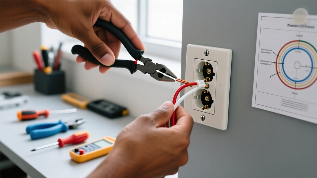
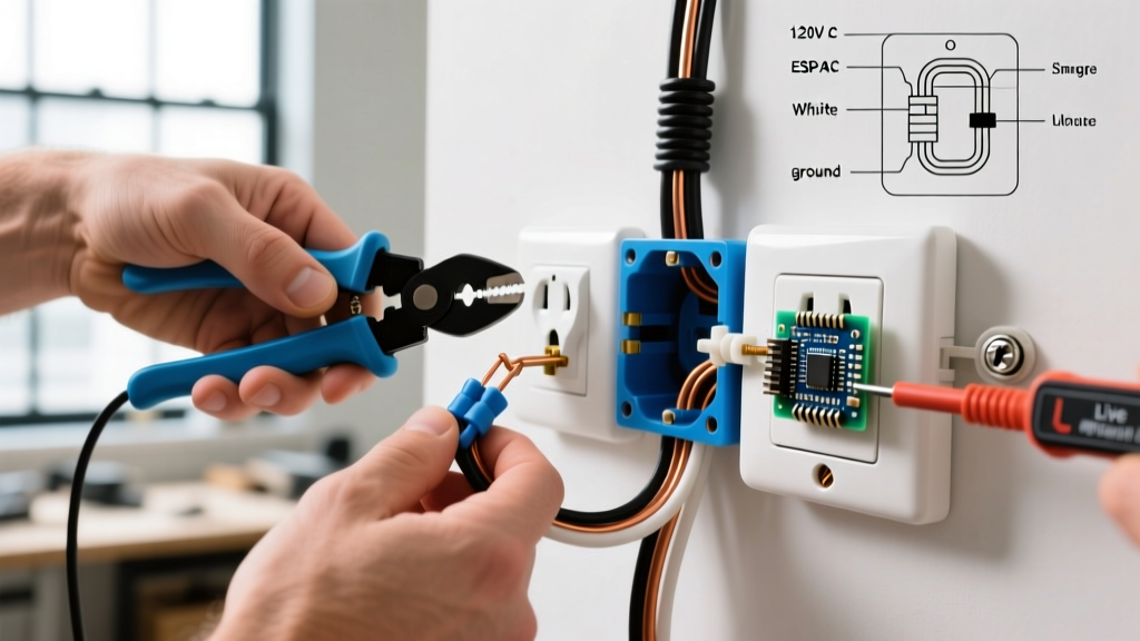
Using the 14 AWG hole on your Klein Tools wire stripper, strip exactly 3/4 inch of insulation from the black and white wires. Do not score or nick the copper conductor; a nicked wire creates a localized hot spot that can lead to thermal failure over time. Straighten any severe bends in the wire using the holes in the wire stripper jaws to ensure the wire sits flush against the receptacle yoke.
Step 4: Make the Terminations (The J-Hook Method)
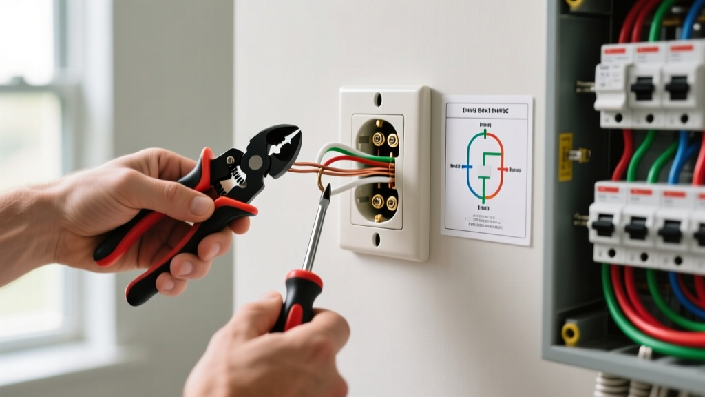
Form a 'J-hook' at the end of the stripped black and white wires using needle-nose pliers. Loop the hook clockwise around the brass (hot) and silver (neutral) terminal screws. Clockwise looping ensures that as you tighten the screw, the loop pulls tighter around the shaft rather than being pushed outward.
- Black Wire: Connects to the brass screw marked 'HOT' or 'LINE'.
- White Wire: Connects to the silver screw marked 'NEUTRAL' or 'WHITE'.
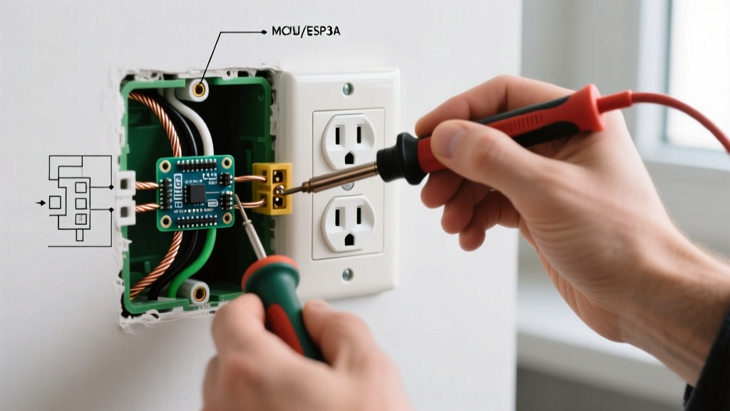
- Bare/Green Wire: Connects to the green grounding screw at the bottom of the yoke.
Step 5: Torque and Fold
Tighten the terminal screws firmly. Leviton specifies a terminal screw torque of roughly 14 in-lbs for standard residential devices. While most DIYers use a standard #2 Phillips screwdriver, be careful not to overtighten, which can strip the brass threads, or undertighten, which causes arcing. Carefully fold the wires back into the box in a 'Z' pattern (ground first, then neutrals, then hots) to avoid pinching the insulation against the sharp edges of the metal or plastic box.
Step 6: Mount, Restore, and Test
Secure the new Leviton T5262-W receptacle to the box using the provided mounting screws. Ensure the yoke is flush and level. Attach the faceplate. Restore power at the breaker panel. Finally, insert your Sperry plug-in tester. Two solid amber lights indicate a 'Correct' wiring configuration. If you see a red light or a missing light, turn the breaker back off immediately and re-check your terminal connections.
Common Beginner Mistakes and Edge Cases
Why You Must Avoid 'Backstab' Push-In Connections
Many modern receptacles feature push-in holes on the back designed for quick wiring. Do not use them. These spring-loaded 'backstab' connections rely on a tiny metal tang biting into the copper. Over time, thermal expansion and contraction from plugging in high-draw devices (like vacuums or space heaters) causes the tang to loosen. According to the National Fire Protection Association (NFPA 70), loose connections are a primary ignition source for residential electrical fires. Always use the side-binding screw terminals for a permanent, high-surface-area connection.
Handling Multiple Cables (Pigtailing)
If your electrical box contains two or more 14/2 cables (meaning you have two black wires, two white wires, and two ground wires), you cannot simply cram two wires under one terminal screw. You must use a 'pigtail.' Twist the two black wires together with a 6-inch piece of spare black 14 AWG wire using a red or yellow wire nut. Connect the free end of the pigtail to the brass terminal screw. Repeat this process for the white neutral wires. Connect all bare ground wires together with a wire nut, leaving one pigtail to connect to the green ground screw on the receptacle.
Frequently Asked Questions
Do I need a Tamper-Resistant (TR) receptacle?
Yes. Under NEC Article 406.12, all 15A and 20A receptacles installed in dwelling units must be Tamper-Resistant. The U.S. Consumer Product Safety Commission (CPSC) strongly advocates for TR outlets, which feature internal spring-loaded shutters that only open when equal pressure is applied to both slots simultaneously (like a standard plug), preventing children from inserting foreign objects.
What is the difference between Line and Load?
On a standard duplex receptacle, there is no functional difference between the top and bottom sets of screws; they are internally bridged by metal break-off tabs. However, if you are installing a GFCI outlet, 'LINE' brings power from the panel, while 'LOAD' sends protected power to downstream outlets. For a standard non-GFCI outlet, simply connect your hot to brass and neutral to silver on either set of screws.
Can I install a 20A outlet on a 15A circuit?
No. While you can legally install a 15A receptacle on a 20A circuit (as long as it is a duplex), you cannot install a 20A receptacle (identified by a T-shaped neutral slot) on a 15A circuit protected by 14 AWG wiring. The breaker would not trip before the smaller wire overheats, creating a severe fire hazard.