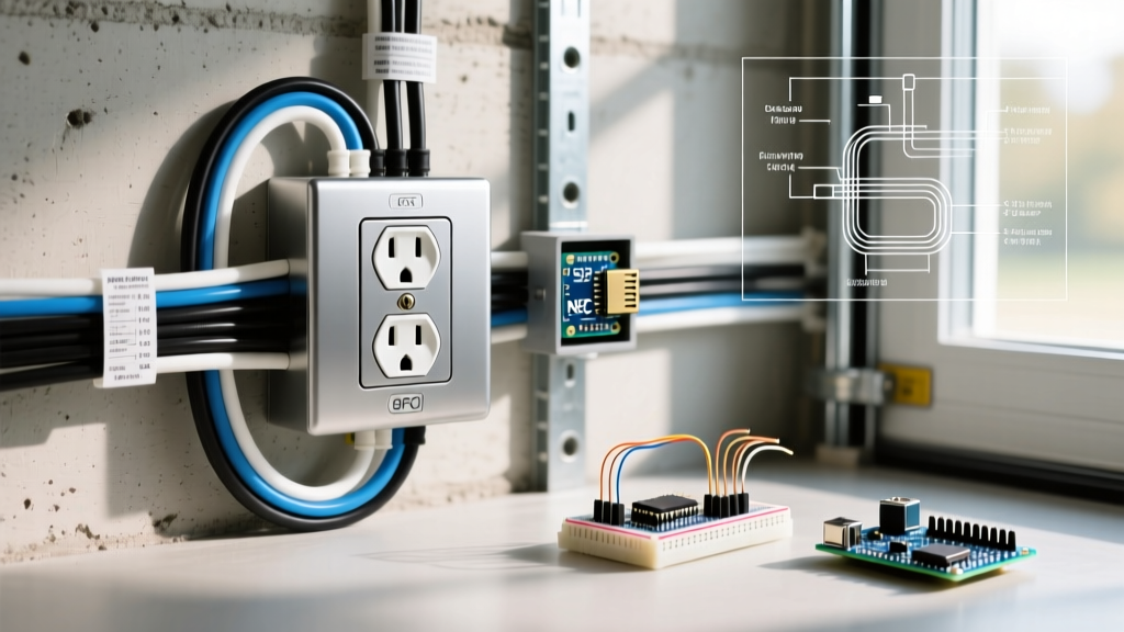

Why Replacing an Old Electrical Outlet is Critical
Every home has them: the loose, discolored, or two-pronged receptacles that refuse to hold a plug securely. Upgrading an old electrical outlet is not merely an aesthetic upgrade; it is a vital fire prevention measure. According to the U.S. Consumer Product Safety Commission (CPSC), aging electrical components, loose connections, and degraded thermoplastic housings are leading causes of residential electrical fires. When the internal brass contacts of a receptacle lose their tension, plugs sit loosely. This poor contact creates electrical arcing and extreme heat, which can easily ignite surrounding wall insulation or wooden studs.
In this comprehensive beginner tutorial, we will walk you through the exact process of safely removing an old electrical outlet and installing a modern, code-compliant replacement. We will cover specific tool requirements, wire preparation techniques, and how to handle tricky edge cases like ungrounded junction boxes.
CRITICAL SAFETY WARNING: Never attempt to work on an electrical circuit without first shutting off the power at the main breaker panel and verifying the absence of voltage with a non-contact tester. Assume all wires are live until proven otherwise.
Diagnostic Matrix: Identifying Your Old Electrical Outlet
Before purchasing a replacement, you must identify the specific type and condition of your old electrical outlet. The National Electrical Code (NEC) mandates specific replacement strategies depending on what is currently inside your wall box.
| Outlet Condition / Type | Visual Identification | Required Replacement Strategy |
|---|---|---|
| Standard 3-Prong (Grounded) | Three slots (two vertical, one round). Wires include Black, White, and Bare Copper. | Replace with a 15A or 20A Tamper-Resistant (TR) duplex receptacle. |
| 2-Prong (Ungrounded) | Two vertical slots only. No bare copper ground wire in the box. | Replace with a GFCI receptacle labeled 'No Equipment Ground' per NEC 406.4(D)(2)(c). |
| Backstabbed (Push-In) | Wires are inserted into holes on the back rather than looped around side screws. | Cut off backstabbed ends, strip fresh wire, and use side-screw termination. |
| Discolored / Melted | Brown burn marks on the plastic face or melted thermoplastic near slots. | Inspect circuit for overloading. Replace outlet and check wire insulation for heat damage. |
Tools and Materials Required
Using the correct tools ensures a safe, secure connection that will last for decades. Avoid cheap, uncalibrated wire strippers that can nick the copper conductor, creating a weak point that will snap under torque.
| Item | Recommended Model | Approx. Cost (2026) | Purpose |
|---|---|---|---|
| Non-Contact Voltage Tester | Klein Tools NCVT1P | $25.00 | Verifies power is off before touching wires. |
| Wire Strippers | Klein Tools 11055 (10-18 AWG) | $28.00 | Strips insulation without nicking copper. |
| Receptacle | Leviton T5325-W (15A TR Duplex) | $3.50 | Code-compliant Tamper-Resistant replacement. |
| Screwdriver | Milwaukee 48-22-2201 | $12.00 | Phillips #2 and Flathead for terminal screws. |
| Needle-Nose Pliers | Channellock 3017CR | $22.00 | Forms perfect clockwise J-hooks on solid wire. |
Step-by-Step Replacement Tutorial
Step 1: Power Down and Verify
Locate your main electrical panel and switch off the breaker controlling the room you are working in. If your panel is not clearly labeled, turn off the main breaker to ensure total safety. Insert your Klein Tools NCVT1P into the top and bottom slots of the old electrical outlet. The tester must remain completely dark and silent. For added certainty, plug in a lamp or a receptacle tester to confirm zero power.
Step 2: Extract and Inspect the Old Outlet
Remove the center cover plate screw and the two long mounting screws securing the receptacle to the junction box. Gently pull the outlet out of the wall. Do not touch the bare wires yet. Take a photo of the existing wiring configuration with your smartphone. Note which wires are connected to the brass (hot) screws, the silver (neutral) screws, and the green (ground) screw. Look closely at the wire insulation; if it is brittle, cracked, or shows signs of heat melting, you may need to consult an electrician to repair the cable inside the wall.
Step 3: Disconnect and Prep the Wires
Loosen the terminal screws to release the wires. If your old electrical outlet was 'backstabbed' (wires pushed into the rear of the device), insert a small flathead screwdriver into the release slots to free them, or simply use your wire strippers to snip the wires flush with the back of the outlet.
Using your Klein Tools 11055 strippers, cut off the old, oxidized ends of the copper wire. Strip exactly 3/4 inch of insulation from the fresh copper. This specific measurement is crucial: too little exposed copper will result in the plastic insulation being pinched under the screw head (causing an open circuit), while too much will leave bare, live copper exposed outside the terminal, creating a shock hazard.
Step 4: Form the J-Hook and Terminate
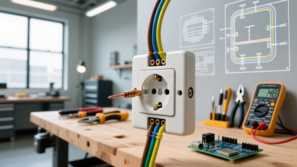
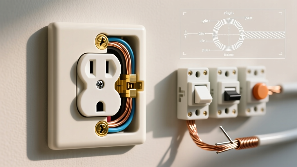
Use your needle-nose pliers to bend the exposed 3/4 inch of copper into a tight 'J' shape or fishhook. This is a critical E-E-A-T technique that many beginners skip. The hook must be oriented so that when you loop it around the terminal screw and tighten it clockwise, the screw pulls the hook tighter rather than pushing it open.
Connect the wires to your new Leviton T5325-W receptacle:
- Bare Copper (or Green): Connect to the Green grounding screw.
- White (Neutral): Connect to the Silver-colored screws.
- Black (Hot): Connect to the Brass-colored screws.
Tighten the screws firmly. According to UL 498 standards, terminal screws on 15A receptacles should be torqued to approximately 12 to 14 inch-pounds. If you do not have a micro-torque screwdriver, tighten the screw until it is firmly snug and the J-hook cannot be wiggled by hand. Never use the push-in backstab holes on the new receptacle; thermal expansion and contraction over the years will cause backstabbed connections to loosen and arc.
Step 5: Mount and Test
Carefully fold the wires into the junction box using a gentle accordion pattern. Push the receptacle flush against the drywall or plaster. Ensure the mounting strap is perfectly level before tightening the top and bottom mounting screws. If the outlet recesses too deeply into the wall (a gap of more than 1/8 inch between the strap and the wall surface), install a plastic box extender ring to meet NEC 314.20 requirements. Attach the cover plate, restore power at the breaker, and test with a 3-light receptacle tester to confirm correct wiring.
Edge Case: What If There Is No Ground Wire?
Many homes built before 1962 feature an old electrical outlet with only two prongs and no equipment grounding conductor in the wall box. You cannot simply install a standard 3-prong outlet and leave the ground screw empty; this creates a severe shock hazard and violates code, as it tricks users into thinking a ground exists.
According to the National Fire Protection Association (NFPA 70 / NEC), specifically Article 406.4(D)(2)(c), you have two legal options for replacing an ungrounded outlet:
- The GFCI Workaround: Replace the old 2-prong outlet with a Ground Fault Circuit Interrupter (GFCI) receptacle. The GFCI does not require a ground wire to provide life-saving shock protection; it monitors the current balance between the hot and neutral wires. You must apply the 'No Equipment Ground' sticker (included in the GFCI box) to the faceplate so future users are aware.
- Rewire the Circuit: Hire a licensed electrician to pull new NM-B (Romex) cable with a dedicated ground wire back to the panel. This is the only way to achieve a true equipment ground for sensitive electronics like surge protectors and desktop computers.
Why 'Backstabbed' Outlets Fail Over Time
If you extract your old electrical outlet and find the wires pushed into the back rather than wrapped around the side screws, you have encountered a 'backstabbed' connection. While legal under older codes, push-in connectors rely on a small internal spring-steel clip to bite into the copper wire. Over decades of electrical load, the wire heats up and expands, then cools and contracts. This continuous thermal cycling slowly works the wire loose from the spring clip. The resulting microscopic gap causes electrical arcing, extreme localized heat, and eventual failure. Always cut backstabbed wires off and use the side-screw termination method detailed in Step 4 when installing your new device.
Frequently Asked Questions
Can I install a 20-Amp outlet on a 15-Amp breaker?
No. NEC Article 210.21(B)(3) strictly prohibits installing a 20A receptacle (identified by a T-shaped neutral slot) on a 15A circuit. A 20A receptacle implies to the user that they can safely draw 20 amps of continuous load, which will overload the 15A breaker and the 14 AWG wire typically used on those circuits. Always match a 15A breaker with a 15A receptacle.
What does 'TR' mean on the new outlet packaging?
TR stands for Tamper-Resistant. As mandated by the Electrical Safety Foundation International (ESFI) and adopted into the NEC, all 15A and 20A residential receptacles must feature internal spring-loaded shutters. These shutters only open when equal, simultaneous pressure is applied to both slots (like a standard plug), preventing children from inserting single objects like paperclips or keys into the hot slot.