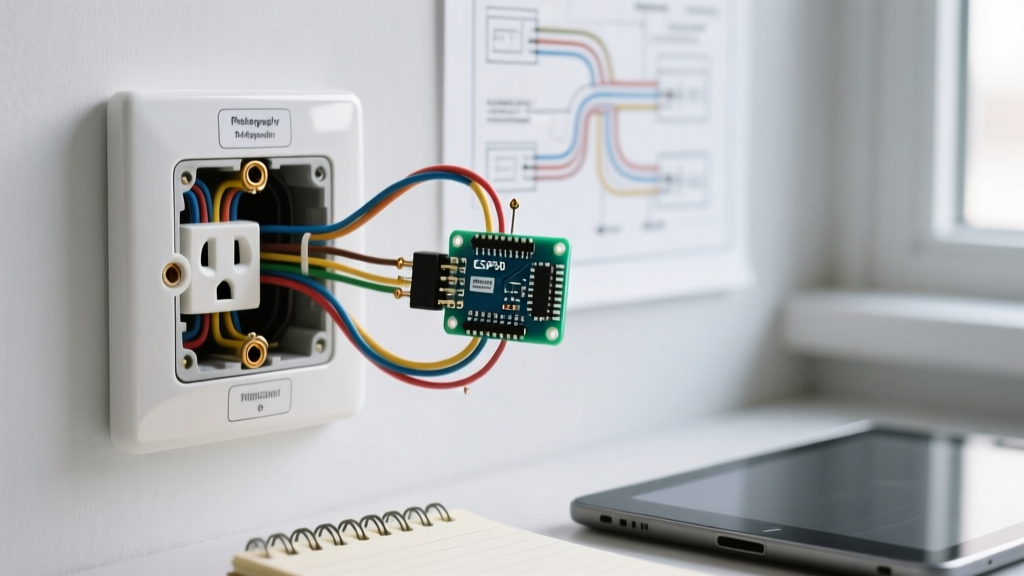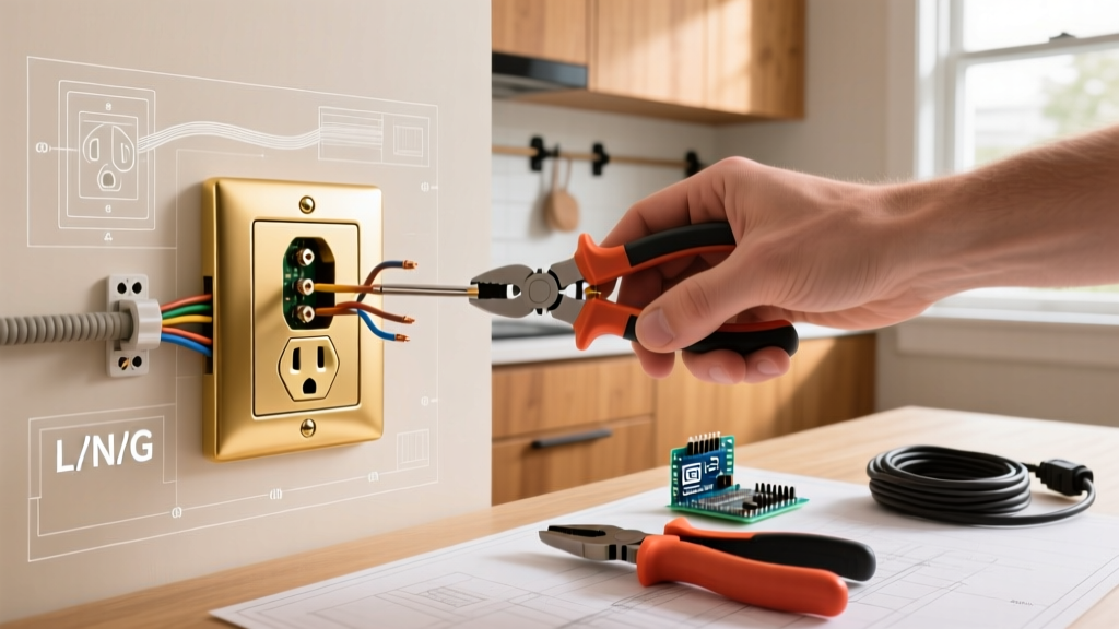

The Evolution of the 3-Way Circuit: Why Upgrade?
If you are dealing with a stiff, arcing, or unreliable 3-way switch, you are not alone. Mechanical 3-way switches endure thousands of physical actuations, and internal brass contacts eventually pit and degrade. In 2026, the standard for residential lighting has shifted heavily toward smart integration and high-end architectural rockers. Whether you are replacing a worn-out toggle with a standard Leviton Decora 5603-2W (approx. $4) or upgrading to a Lutron Caseta smart system, understanding the underlying circuit topology is mandatory.
This comprehensive upgrade guide provides a definitive wiring diagram for 3 way light switch configurations, breaking down the line, load, and traveler relationships. We will cover mechanical replacements, smart switch conversions, and critical National Electrical Code (NEC) compliance metrics to ensure your upgrade is both functional and safe.
Anatomy of a 3-Way Switching System
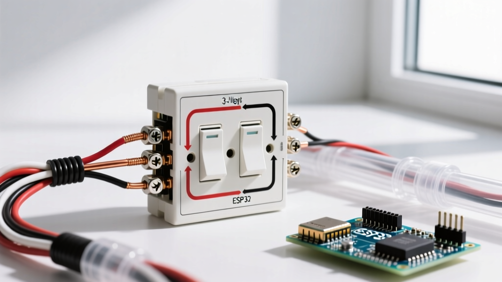
Unlike a single-pole switch that simply breaks the hot wire, a 3-way system creates an alternate-path circuit. Power enters one switch box, travels through a pair of 'traveler' wires to the second switch box, and finally exits to the light fixture.
Terminal Identification
- Common Terminal (COM): Usually a darker-colored screw (black or dark bronze). This connects to either the Line (power source) or the Load (light fixture).
- Traveler Terminals (T1 & T2): Two lighter brass-colored screws. These carry the alternating current between the two switches.
- Ground Terminal: Green screw, mandatory for all modern metal and plastic faceplates.
Expert Insight: Never rely on wire colors in an existing 3-way setup to identify Line, Load, or Travelers. Previous homeowners or electricians often use whatever wire is left on the spool. Always verify with a multimeter.
Master Wiring Diagram for 3 Way Light Switch Setups
Below is the logical mapping for a standard 3-way circuit. This diagram assumes a 14/2 NM-B cable from the panel, 14/3 NM-B between the switches, and 14/2 NM-B to the light fixture.
| Cable / Source | Switch 1 (Line Box) | Switch 2 (Load Box) | Light Fixture |
|---|---|---|---|
| Panel Feed (14/2) | Black (Hot) to COM White (Neutral) wire-nutted Bare (Ground) to Box/Switch | N/A | N/A |
| Traveler Run (14/3) | Red to T1 Black to T2 White wire-nutted Bare to Ground | Red to T1 Black to T2 White to COM (re-identified) Bare to Ground | N/A |
| Fixture Feed (14/2) | N/A | N/A | Black to Hot White to Neutral Bare to Ground |
Note: In some homes, the 'Load' wire is pulled through the 14/3 cable using the white wire as a hot feed to the fixture. If this is the case, the white wire must be wrapped in black electrical tape at both ends to re-identify it as a hot conductor, per NEC Article 200.7.
Step-by-Step Mechanical Replacement Guide
Upgrading to a modern rocker switch like the Leviton Decora 5603 or Lutron Claro S-3PSH ($14) requires precise identification of the Common wire.
Step 1: Isolate and Verify Power
Turn off the breaker and verify dead circuits using a non-contact voltage tester like the Klein Tools NCVT-2 ($25). Test the tester on a known live circuit first to ensure the battery is functional.
Step 2: Identify the 'Common' Wire on the Old Switch
Before disconnecting anything, look at the old switch. Identify the single screw that is a different color (usually black). The wire attached to this screw is your critical Line or Load wire. Tag it with blue painter's tape.
Step 3: Map the Travelers
Disconnect the two brass-colored screws. These are your travelers. It does not matter which traveler goes to which brass screw on the new switch; they are interchangeable.
Step 4: Terminate and Torque
Connect the tagged Common wire to the black screw on the new switch. Connect the travelers to the brass screws. Wrap the terminals with 3M Super 33+ electrical tape to prevent accidental shorting against the metal box. Secure the switch with 6-32 machine screws, ensuring it sits plumb.
Upgrade Path B: Smart Switch Conversions (2026 Standards)
Converting a 3-way circuit to a smart switch is the most requested upgrade in modern renovations. However, standard smart switches require a Neutral wire to power their internal Wi-Fi/Zigbee radios. In many older 3-way setups, only one of the two boxes contains a neutral wire.
Solution 1: The Neutral-Free Bypass (Lutron Caseta)
If your switch boxes lack a neutral wire, the Lutron Caseta PD-5S-DV (approx. $70) is the industry standard.
- How it works: You wire the Caseta switch in the box that has the Line, Load, and Neutral (or use the Lutron PD-5S-DV which doesn't strictly require a neutral for switching, though a neutral is required for the companion Pico bracket if hardwired).
- The Second Box: The second 3-way box is entirely bypassed. You cap the wires in the wall and mount a battery-powered Lutron Pico PJ2-3BRL remote over a blank faceplate. This eliminates the need to pull new 14/4 cable through your drywall.
Solution 2: The True Smart 3-Way (Kasa KS230)
If both boxes have neutral wires (common in post-2011 construction where NEC mandated neutrals at switch loops), the Kasa KS230 Smart 3-Way Kit ($35) is highly cost-effective. The main smart switch requires Line, Load, Neutral, Ground, and one Traveler. The companion switch requires Line/Load, Neutral, Ground, and the corresponding Traveler.
Comparison Matrix: Mechanical vs. Smart 3-Way Upgrades
| Feature | Standard Rocker (e.g., Leviton Decora) | Smart Switch (e.g., Kasa KS230) | Smart + Remote (e.g., Lutron Caseta) |
|---|---|---|---|
| Material Cost | $4 - $14 | $35 - $45 | $70 - $110 |
| Neutral Wire Required? | No | Yes (Both Boxes) | No (Switch) / Optional (Pico) |
| Install Time | 10 - 15 Minutes | 30 - 45 Minutes | 45 - 60 Minutes |
| Box Depth Needed | Standard (18 cu in) | Deep (22+ cu in) | Standard (18 cu in) |
| App / Voice Control | No | Yes (Matter/Thread ready) | Yes (Requires Hub) |
Advanced Troubleshooting & Edge Cases
Even with a perfect wiring diagram for 3 way light switch layouts, DIYers frequently encounter specific failure modes during upgrades.
Edge Case 1: The 'Independent' Switch Phenomenon
Symptom: Switch A only works if Switch B is in the 'up' position. Switch B only works if Switch A is 'down'.
Diagnosis: You have wired a Line or Load wire to a Traveler terminal, or crossed the travelers with the common wire.
Fix: Re-verify the Common wire. The Common terminal must exclusively connect to the singular wire that either originates from the breaker panel or feeds directly to the light fixture.
Edge Case 2: Phantom Voltage on Travelers
Symptom: Your digital multimeter reads 40V-60V on the disconnected traveler wires when the circuit is live.
Diagnosis: This is capacitive coupling (phantom voltage) induced by the parallel hot wire inside the 14/3 Romex jacket.
Fix: Ignore it. Use a low-impedance multimeter (like the Fluke 117 with Auto-V/LoZ) or a solenoid voltage tester (Wiggy) to confirm the wire is actually dead before touching it.
NEC Compliance and Box Fill Calculations
When upgrading to smart switches, physical space becomes a major hurdle. Smart switches are significantly deeper than mechanical toggles, often protruding 1.5 inches into the wall cavity. Furthermore, the addition of wire nuts, pigtails, and the device itself alters the 'box fill' calculation mandated by the National Fire Protection Association (NFPA) under NEC Article 314.16.
For 14 AWG wire, each conductor, clamp, and device counts as 2.0 cubic inches. A standard single-gang 'nail-on' box is only 18 cubic inches. If your smart switch requires pigtailing the neutral and ground, you can easily exceed the legal box fill, creating a severe fire hazard due to heat entrapment.
The 2026 Solution: If your box is overcrowded, install an Arlington BE1 Non-Metallic Box Extender ($3). This adds crucial cubic volume, ensures the smart switch sits flush without crushing the Romex jackets, and maintains strict NEC compliance. Always refer to OSHA electrical safety guidelines and local municipal codes before finalizing any permanent wiring modifications. According to the U.S. Department of Energy, properly installed smart switches and dimmers can reduce residential lighting energy consumption by up to 15% annually, making this upgrade both a safety and financial improvement.