
The Critical Distinction: TT-30R vs. NEMA 10-30
When searching for a reliable wiring diagram for 30 amp RV outlet setups, the most critical factor is understanding the fundamental difference between an RV receptacle and a standard household dryer outlet. A 30-amp RV outlet utilizes a NEMA TT-30R configuration. This is a 120-volt AC, single-phase, 3-wire grounding receptacle.
The most dangerous mistake DIYers make is confusing the TT-30R with a NEMA 10-30 or NEMA 14-30 dryer outlet, which operates at 240 volts. Wiring a 240-volt feed into a TT-30R receptacle will instantly destroy your RV's onboard converter, fry sensitive electronics, and create a severe fire hazard. According to NFPA 70 (National Electrical Code) Article 551, RV park and home RV supply circuits must strictly adhere to 120V nominal specifications. This guide provides the exact wiring diagram, component matrix, and torque specifications required for a safe, code-compliant installation in 2026.
2026 Component Checklist & Pricing Matrix
Before pulling wire, verify your materials. Using undersized breakers or non-marine-grade outdoor enclosures leads to premature failure. Below is the recommended bill of materials for a standard 50-foot residential run.
| Component | Recommended Model (2026) | Specification | Avg. Cost |
|---|---|---|---|
| Receptacle | Leviton 278-S00 or Hubbell 9450A | NEMA TT-30R, 125V, 30A | $16 - $24 |
| Circuit Breaker | Square D QO130 or Siemens Q130 | 30A, Single-Pole, 120/240V | $14 - $19 |
| Wire (Indoor) | Southwire 10/2 NM-B (Romex) | 10 AWG Copper with Ground | $0.85 / ft |
| Wire (Outdoor/Conduit) | THHN/THWN-2 Stranded | 10 AWG (Black, White, Green) | $0.60 / ft |
| Weatherproof Enclosure | TayMac MM410C or similar | Extra-duty, in-use cover | $22 - $30 |
Core Wiring Diagram: Panel to TT-30R Receptacle
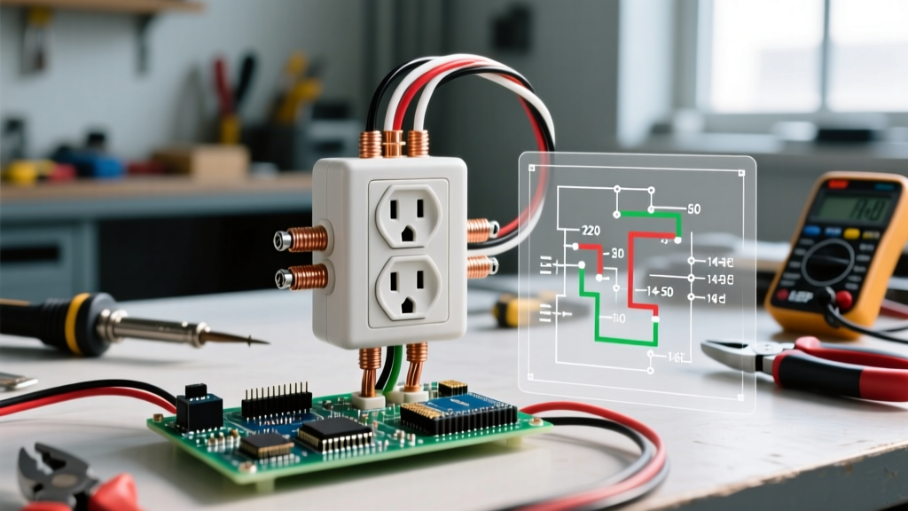
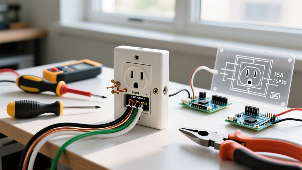
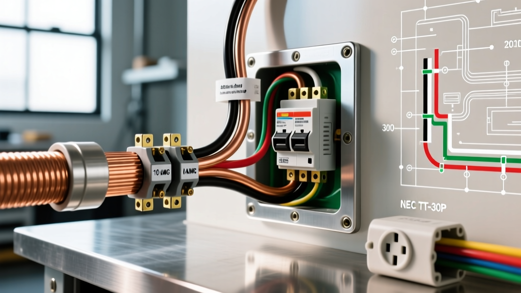
The wiring topology for a TT-30R is straightforward but demands strict attention to terminal identification. Unlike standard NEMA 5-15R household outlets, the physical blade orientation on a TT-30P (plug) dictates specific terminal mapping on the receptacle back.
Terminal Pinout Reference
- Hot (Line 1): Black wire connects to the Brass / X terminal.
- Neutral: White wire connects to the Silver / W terminal.
- Equipment Ground: Bare copper or green wire connects to the Green / G terminal.
Expert Warning: Never bond the neutral and ground at the RV receptacle. The neutral-to-ground bond must only occur at the main service disconnect panel. Bonding them at the outlet creates a parallel neutral path, which can energize the RV chassis and cause lethal shock hazards.
Step-by-Step Installation Flow
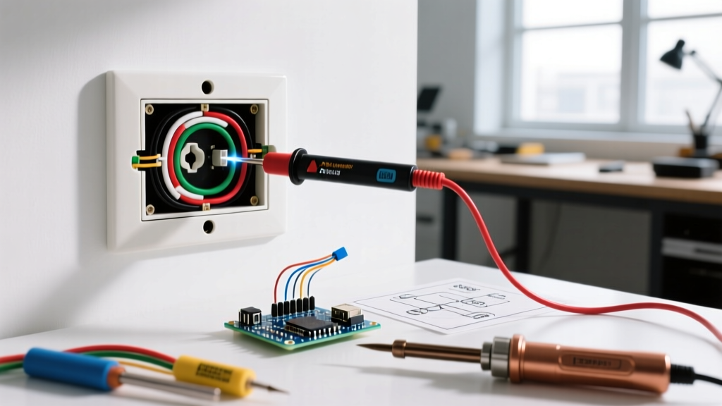
- De-energize and Verify: Turn off the main breaker. Use a non-contact voltage tester and a multimeter to confirm 0V at the panel bus bars.
- Install the Breaker: Snap the 30A single-pole breaker (e.g., Square D QO130) into an available slot on the hot bus bar. Connect the black circuit wire to the breaker's load terminal. Torque to the manufacturer's spec (typically 35-40 in-lbs for QO series).
- Route and Strip the Cable: Run the 10/2 NM-B cable to the outlet location. Strip the outer jacket, leaving at least 8 inches of working length. Strip exactly 5/8 inch of insulation from the individual conductors using a 10 AWG calibrated wire stripper.
- Terminate the Ground: Loop the bare copper wire clockwise around the green ground screw on the TT-30R receptacle. Tighten to 14-18 in-lbs. A loose ground is the primary cause of thermal runaway in RV pedestals.
- Terminate the Neutral: Connect the white wire to the silver 'W' terminal. Ensure no bare copper is exposed outside the terminal clamp.
- Terminate the Hot: Connect the black wire to the brass 'X' terminal.
- Secure and Weatherproof: Push the wires neatly into the box, mount the receptacle, and attach the extra-duty in-use cover. Seal all conduit and box entry points with silicone or duct seal to prevent moisture ingress, which causes rapid galvanic corrosion on brass terminals.
Advanced Edge Cases: Voltage Drop Calculations
The NEC recommends a maximum voltage drop of 3% for branch circuits. A standard 10 AWG copper wire has a resistance of approximately 1.018 ohms per 1,000 feet. If your RV outlet is located far from the main panel, you must adjust your wire gauge to prevent your RV's air conditioning compressor from stalling due to low voltage.
Distance vs. Wire Gauge Matrix (at 30A Load)
| One-Way Run Distance | Total Wire Length | 10 AWG Voltage Drop | 8 AWG Voltage Drop | Required Action |
|---|---|---|---|---|
| 25 Feet | 50 Feet | 1.52V (1.2%) | 0.96V (0.8%) | 10 AWG is sufficient. |
| 50 Feet | 100 Feet | 3.05V (2.5%) | 1.92V (1.6%) | 10 AWG is acceptable; 8 AWG is optimal. |
| 75 Feet | 150 Feet | 4.58V (3.8%) | 2.89V (2.4%) | Upgrade to 8 AWG. |
| 100 Feet | 200 Feet | 6.10V (5.0%) | 3.85V (3.2%) | Upgrade to 6 AWG. |
Note: When upsizing wire for voltage drop, you must ensure the larger gauge wire physically fits into the breaker and receptacle terminals. If a 6 AWG wire will not fit into the TT-30R terminal, use a 6-to-10 AWG reducing lug or pigtail, provided the pigtails are kept under 12 inches and the overcurrent protection remains 30A.
Common Failure Modes & Thermal Diagnostics
Even with a perfect wiring diagram, environmental and mechanical factors can degrade an RV outlet over time. As an electrical professional, you should be aware of these specific failure modes:
- Thermal Creep (Cold Flow): Copper wire expands and contracts under heavy continuous loads (like running a 15,000 BTU RV AC unit). Over 12-18 months, this cycle can loosen terminal screws. Solution: Perform an annual torque check or use receptacles with internal torque-limiting clamps.
- Blade Oxidation: The TT-30P plug blades on the RV side often oxidize if left exposed to coastal or humid environments. This increases contact resistance, generating heat at the receptacle face. Solution: Clean RV plug blades annually with fine-grit sandpaper and apply a dielectric grease like NO-OX-ID A-Special.
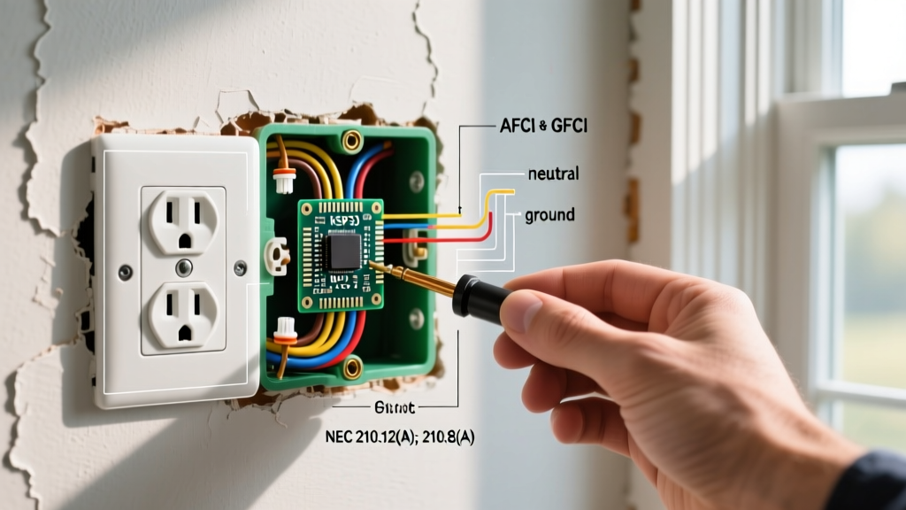
- GFCI Nuisance Tripping: While NEC Article 210.8(F) requires GFCI protection for outdoor receptacles, some older RV onboard chargers and converters leak enough milliamps to trip a standard 5mA GFCI breaker. If you experience persistent tripping, verify the RV's internal converter health before bypassing safety codes. The RV Industry Association strongly advises against removing GFCI protection as a troubleshooting shortcut.
Frequently Asked Questions (FAQ)
Can I use a 30-amp double-pole breaker for a TT-30R outlet?
No. A double-pole breaker provides 240 volts by connecting to both hot bus bars in your panel. A TT-30R requires exactly 120 volts. You must use a single-pole 30-amp breaker. If you only have space for a double-pole breaker in your panel, you can wire only one of the poles and cap the other, but it is highly recommended to use the correct single-pole breaker to avoid future confusion and safety hazards.
Is a GFCI breaker required for an outdoor RV outlet in 2026?
Yes, under recent NEC adoptions (Article 210.8(F)), all outdoor receptacles rated 150V to ground or less and 50A or less must have GFCI protection. However, if the RV outlet is installed in a dedicated RV park pedestal governed strictly by Article 551, there may be specific exceptions regarding ground-fault protection of equipment (GFPE) vs. personnel (GFCI). For a residential driveway installation, your local AHJ (Authority Having Jurisdiction) will almost certainly mandate a 30A GFCI breaker.
Why is my RV AC compressor humming but not starting when plugged into my new 30A outlet?
This is a classic symptom of voltage drop. When the compressor attempts to start, it draws a massive locked-rotor amperage (LRA) spike, often exceeding 40 amps for a fraction of a second. If your wire run is too long (using 10 AWG over 75+ feet), the voltage at the receptacle can temporarily sag below 105V, causing the compressor to stall and hum. Check your voltage under load using a multimeter; if it drops below 110V, you must upgrade your feeder wire gauge.
For further reading on recreational vehicle electrical safety standards and manufacturing codes, consult the resources provided by the Schneider Electric QO Load Center documentation regarding proper breaker torque and bus bar seating, ensuring your entire circuit from panel to pedestal is optimized for heavy continuous RV loads.