
Understanding the Daisy-Chain Method
Learning how to add an electrical outlet to an existing outlet is one of the most practical and cost-effective DIY electrical upgrades you can perform. Often referred to as 'daisy-chaining,' this process involves extending an existing branch circuit to power a new receptacle. Whether you need extra power for a home office setup, a wall-mounted TV, or kitchen appliances, adding a new outlet saves you from running a completely new circuit from your main breaker panel.
However, electrical work demands strict adherence to safety protocols and the National Electrical Code (NEC). According to the National Fire Protection Association (NFPA), electrical failures or malfunctions are a leading cause of home fires. This guide provides a comprehensive, step-by-step installation framework with 2026 industry standards, precise tool recommendations, and critical box-fill calculations to ensure your project is both safe and code-compliant.
Essential Tools and Materials
Before cutting into any drywall, gather the following professional-grade tools and materials. Do not compromise on wire strippers or voltage testers, as these are your primary safety and quality assurance devices.
- Voltage Tester: Klein Tools NCVT-2 Non-Contact Voltage Tester (Dual-range, $25-$30).
- Wire Strippers: Knipex 1101600 or Klein 11057 (Precision 14/12 AWG stripping, $35).
- Old Work Box: Carlon B618R 1-Gang Non-Metallic Old Work Box (18 cubic inches, $3).
- Receptacle: Leviton T5320-W 15A Tamper-Resistant (TR) Duplex Receptacle ($4).
- Cable: Southwire 14/2 or 12/2 NM-B Romex (depending on circuit amperage, $1/ft).
- Connectors: Wago 221-412 Lever Nuts or Ideal 341 Orange Wire-Nuts.
- Fish Tape: Klein Tools 50 ft. Steel Fish Tape ($25).
Matching Wire Gauge to Circuit Amperage
A critical first step is identifying the amperage of the existing circuit. You must match the new cable and receptacle to the existing breaker size. Mixing wire gauges on a single circuit is a severe fire hazard and a direct violation of NEC Article 240.4.
| Circuit Breaker | Required NM-B Cable | Receptacle Rating | Max Box Fill (14/12 AWG) |
|---|---|---|---|
| 15 Amp | 14/2 AWG | 15A (or 20A rated) | 2.0 cu in / 2.25 cu in per wire |
| 20 Amp | 12/2 AWG | 20A (or 15A rated*) | 2.25 cu in per wire |
*Note: NEC 210.21(B)(3) allows 15A receptacles on a 20A circuit as long as there is more than one receptacle on the circuit (a duplex outlet counts as two).
Step-by-Step Installation Guide
Step 1: Kill the Power and Verify
Navigate to your main electrical panel and turn off the breaker controlling the existing outlet. Use your Klein Tools NCVT-2 to test the top and bottom slots of the existing receptacle. Never assume a breaker label is correct. Plug a lamp or a digital multimeter into the outlet to provide a secondary, definitive confirmation that the circuit is dead. The Consumer Product Safety Commission (CPSC) strongly advises double-verifying power status before touching any bare conductors.
Step 2: Cut the Drywall and Mount the Old Work Box
- Use a stud finder (like the Franklin Sensors 710-301) to locate the wooden studs near your desired new outlet location. You must place the new box in the hollow cavity between studs.
- Hold the Carlon B618R old work box against the drywall and trace its outline with a pencil.
- Cut along the inside of the traced line using a drywall jab saw. Keeping the cut slightly inside the line ensures the box's mounting flanges will grip the drywall securely.
- Insert the box into the hole, pull the plastic mounting wings tight against the back of the drywall using a Phillips screwdriver, and tighten until flush.
Step 3: Fish the NM-B Cable
Feed your fish tape from the new outlet hole up or down through the wall cavity toward the existing outlet. If you are working on an interior wall without fire blocks, this is relatively straightforward. Once the fish tape reaches the existing outlet cavity, hook the tape, attach your NM-B cable (stripped of its outer jacket for the last 12 inches to reduce friction), and pull it back to the new box. Leave at least 8 inches of slack in both boxes, as required by NEC 300.14.
Step 4: Calculate Box Fill (Crucial Code Requirement)
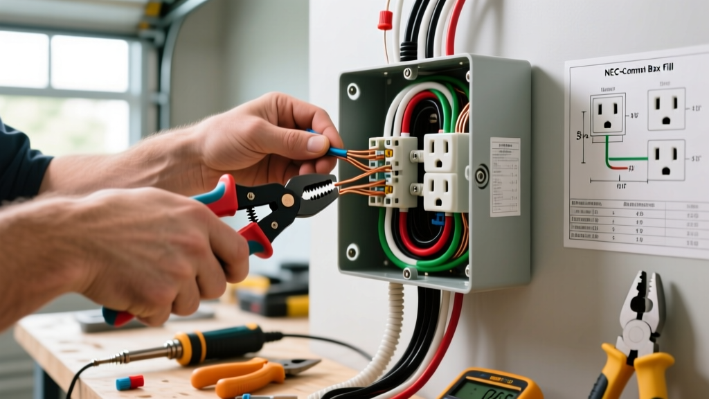
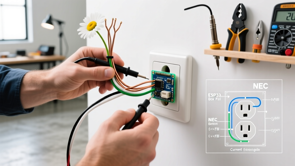
Before wiring, you must ensure the existing electrical box has enough physical volume to handle the new wires. Overcrowded boxes trap heat and cause arc faults. According to NEC Article 314.16, you must calculate the 'box fill' based on the largest wire entering the box.
Box Fill Calculation Example (14 AWG Wire):
Each current-carrying conductor (hot/neutral) counts as 2.0 cubic inches.
All grounding wires combined count as 2.0 cubic inches.
The receptacle device counts as 4.0 cubic inches (2 volumes).
All internal clamps count as 2.0 cubic inches.
If your existing standard 12-cubic-inch box already has one cable entering, one leaving, and a receptacle, it is at 18 cubic inches and is already overfilled. You must upgrade to a deep 22-cubic-inch box or use a surface-mounted raceway.
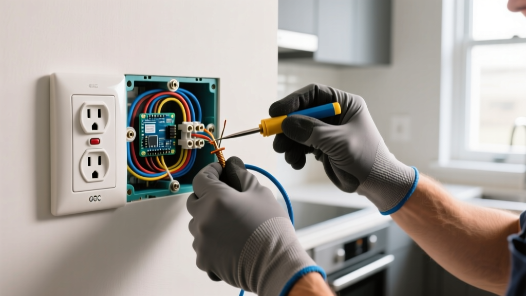
Step 5: Pigtail the Existing Outlet
You must connect the new cable to the existing power source using 'pigtails.' Never push two wires into a single backstab (push-in) terminal. Backstab connections rely on a single metal spring clip that loosens over time due to thermal expansion, leading to high-resistance arcing and fires. Furthermore, NEC 110.14(A) prohibits looping two separate wires under a single terminal screw.
- Strip 3/4 inch of insulation from the black, white, and bare copper wires of both the existing circuit and the new cable.
- Cut three 6-inch pigtail wires (one black, one white, one bare) and strip them.
- Join the existing black wire, the new black wire, and the black pigtail using a Wago 221 lever nut. Connect the pigtail to the brass (hot) screw on the existing receptacle.
- Repeat for the white (neutral) wires, connecting the pigtail to the silver screw.
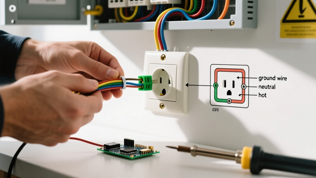
- Join all bare copper ground wires with the ground pigtail, and attach it to the green grounding screw on the receptacle and the metal box (if applicable).
Step 6: Wire the New Receptacle
At the new outlet location, strip the NM-B jacket back to where it enters the box, leaving exactly 1/4 inch of jacket inside the box to protect the wire insulation from the sharp plastic edges. Strip 3/4 inch of insulation from the individual conductors. Wrap the black wire clockwise around the brass terminal screw and tighten. Wrap the white wire clockwise around the silver terminal screw. Connect the bare copper to the green ground screw. Ensure no bare copper is exposed outside the terminal connections.
Edge Cases: GFCI and AFCI Considerations
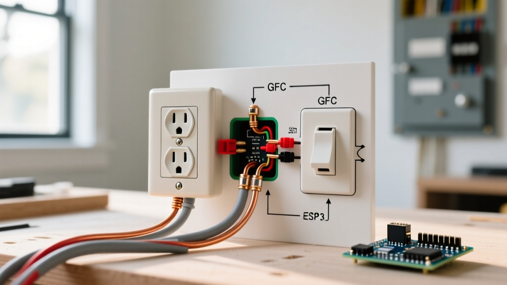
If the existing outlet is a GFCI (Ground Fault Circuit Interrupter), commonly found in kitchens, bathrooms, and garages, you have two choices for the new downstream outlet:
- Standard Protection: Connect the new cable to the 'LOAD' terminals of the existing GFCI. This extends GFCI protection to the new outlet.
- Standard Power Only: Connect the new cable to the 'LINE' terminals (using pigtails). The new outlet will have power but will not trip if a ground fault occurs at the new location.
Additionally, if the circuit supplies a bedroom or living room, NEC 210.12 requires the entire branch circuit to be protected by an AFCI (Arc Fault Circuit Interrupter) breaker. Adding a standard receptacle downstream does not negate this requirement; the breaker at the panel must remain AFCI-compliant.
Final Testing and Safety Verification
Once both receptacles are secured into their boxes and the faceplates are installed, restore power at the breaker panel. Use a standard 3-light receptacle tester (like the Gardner Bender GFI-3501) to verify correct wiring. The tester should display two yellow lights, indicating 'Correct Wiring.' Test the GFCI reset buttons if applicable. Finally, torque the terminal screws to the manufacturer's specifications—typically 14 in-lbs for Leviton 15A/20A residential receptacles—to ensure long-term mechanical stability and prevent thermal runaway.