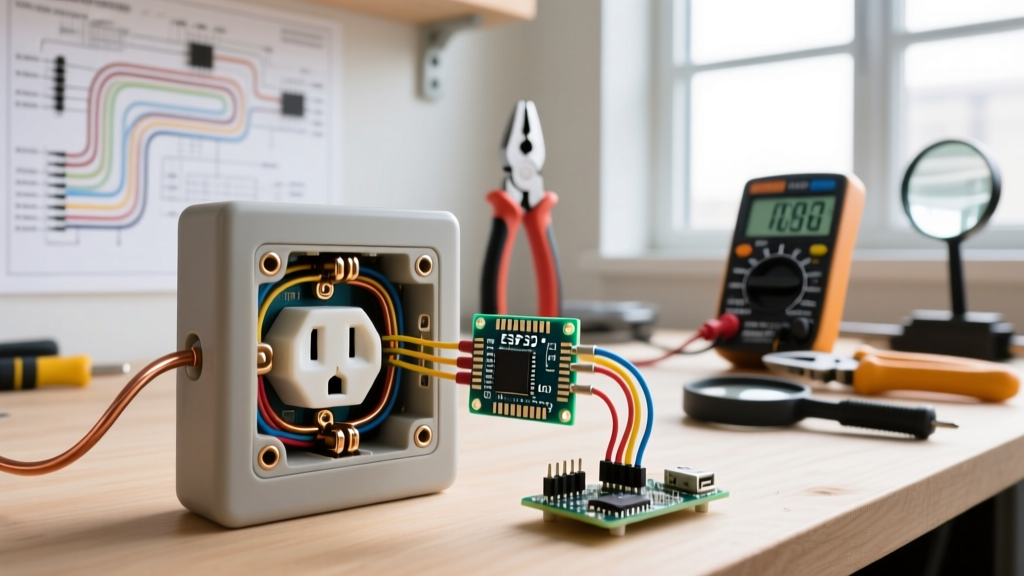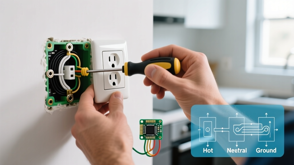

The Diagnostic Approach: Why Did the Outlet Fail?
When homeowners ask, "how do you replace an electrical outlet?", they are usually focused on the physical swap. However, as a senior electrical technician, I can tell you that simply swapping a dead receptacle without diagnosing the root cause is a recipe for recurring failures, arcing, and potential electrical fires. In 2026, residential circuits are under more stress than ever. The proliferation of continuous smart-home hubs, high-draw kitchen appliances, and portable EV chargers means that standard 15-amp and 20-amp receptacles are operating closer to their thermal limits.
Before you touch a screwdriver, you must understand why the existing outlet failed. Was it a loose neutral? A degraded push-in connection? Galvanic corrosion on aluminum wiring? This guide walks you through the diagnostic troubleshooting process and the precise, code-compliant steps to replace the outlet permanently.
Common Failure Modes in Residential Receptacles
According to the Electrical Safety Foundation International (ESFI), loose connections and degraded terminals are leading causes of residential electrical fires. Here are the three most common failure modes you will encounter:
- Backstabbed (Push-In) Connections: Builder-grade outlets often use spring-steel push-in terminals. Over years of thermal cycling (expansion and contraction from load heating), these springs lose tension. The wire loosens, resistance increases, and the terminal melts.
- Thermal Creep on Screw Terminals: If the copper wire was not looped correctly (e.g., the J-hook was oriented counter-clockwise or stripped too far), the screw can loosen over time. This creates a high-resistance fault, leading to scorch marks on the thermoplastic yoke.
- Aluminum Wiring Incompatibility: Homes built between 1965 and 1973 often have aluminum branch wiring. If a standard copper-rated (CU) receptacle was installed on aluminum wire, galvanic corrosion will cause the connection to fail and overheat. You must use CO/ALR rated devices.
CRITICAL SAFETY WARNING: Never assume a circuit is dead just because the breaker is in the 'OFF' position. Multi-wire branch circuits (MWBC) or mislabeled panels can leave the neutral or secondary hot leg energized. Always verify with a calibrated tester.
Phase 1: Pre-Removal Testing & Verification
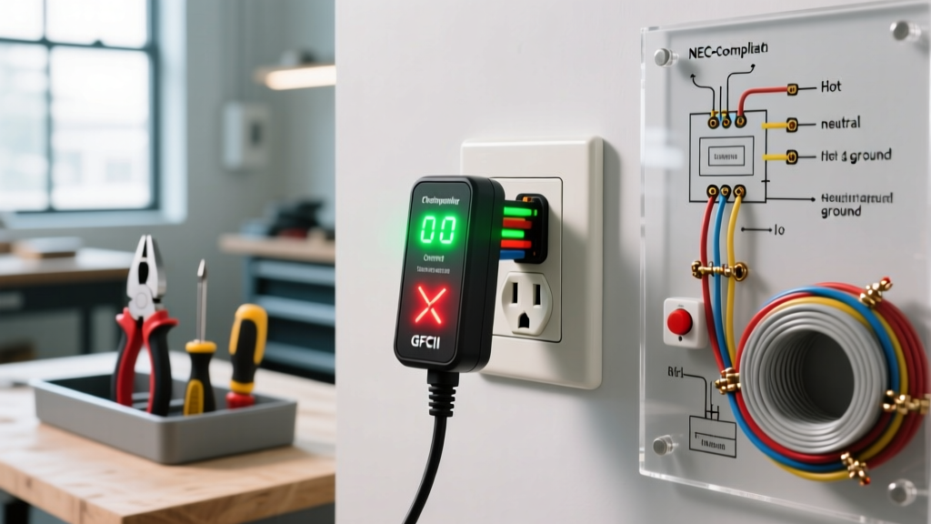
Before removing the faceplate, perform a non-invasive diagnostic test. Insert a standard receptacle tester (like the Sperry ET6401 or Klein Tools RT250) into the outlet. This will immediately reveal hidden wiring faults that a simple voltage sniffer cannot detect.
| Light Pattern (Standard 3-Light Tester) | Diagnosis | Required Action Before Replacement |
|---|---|---|
| Yellow, Yellow, OFF | Correct Wiring | Safe to proceed with standard swap. |
| OFF, Yellow, Yellow | Open Hot | Check upstream connections; breaker may be tripped or backstab failed upstream. |
| Yellow, OFF, Yellow | Open Neutral | Do not replace yet. Trace the neutral wire back to the panel or previous junction. |
| Yellow, OFF, OFF | Hot/Neutral Reversed | Critical fault. Verify line/load orientation before installing new receptacle. |
| OFF, Yellow, Red | Hot/Ground Reversed | Stop immediately. This indicates a severe miswire at the panel. Call an electrician. |
Phase 2: Safe Extraction and Visual Inspection
Once you have killed the power at the breaker and verified it is dead using a non-contact voltage tester (NCVT) like the Klein Tools NCVT-2, remove the faceplate and extract the receptacle from the gang box.
Before disconnecting a single wire, take a photograph with your smartphone. If the outlet is part of a daisy-chain (pass-through) circuit, you will have two sets of hot and neutral wires. If it is a split-receptacle (common in kitchens where the top and bottom halves are on different breakers), you will see a broken brass fin on the hot side.
Inspecting the Old Hardware
Look closely at the old outlet. If the thermoplastic face is brown or melted near the push-in holes, the failure was caused by backstabbing. Cut off the damaged portion of the wire using your wire strippers, as the copper may have become annealed (softened) and brittle from excessive heat. Strip back to fresh, shiny copper before terminating the new device.
Phase 3: How Do You Replace an Electrical Outlet (Step-by-Step)
Now that you have diagnosed the circuit and prepped the wires, it is time to install the new receptacle. For general residential use in 2026, I strongly recommend upgrading to commercial-grade, tamper-resistant (TR) duplex receptacles, such as the Leviton T5320-W (approx. $4.50 each). They feature thicker internal brass contacts and superior clamping force compared to $1.25 builder-grade units.
- Strip the Wires Precisely: Use the 14 AWG or 12 AWG hole on your wire strippers. Strip exactly 5/8 of an inch of insulation. If you strip too much, bare wire will be exposed outside the terminal, creating a shock hazard. If too little, the insulation will bind under the screw plate, causing a loose connection.
- Form the J-Hook: Use needlenose pliers to bend the exposed copper into a tight 'J' hook. The hook must curve clockwise.
- Seat the Wire on the Screw: Wrap the clockwise hook around the brass (hot) or silver (neutral) screw. As you tighten the screw clockwise, it will naturally pull the wire loop tighter around the terminal shaft. Never use the backstab holes on the new receptacle.
- Grounding: Connect the bare copper or green wire to the green grounding screw. If the box is metal, you must also run a grounding pigtail from the box to the receptacle yoke.
The 2026 NEC Torque Requirement (Crucial Step)
One of the most vital updates in modern electrical code that DIYers miss is NEC 110.14(D). The National Electrical Code (NEC) now strictly requires that all terminations be tightened to the manufacturer's specified torque using a calibrated tool.
For a standard 15A or 20A Leviton or Hubbell receptacle, the specified torque is typically 0.75 N·m (0.6 lb-in). Hand-tightening with a standard screwdriver is no longer acceptable for code compliance and often leads to under-torqued connections. Invest in a VDE-insulated torque screwdriver, such as the Milwaukee 48-22-2901 (approx. $65), which allows you to dial in the exact inch-pound rating. This single step eliminates 90% of future thermal creep failures.
Post-Installation Troubleshooting Matrix
After carefully pushing the wires back into the box, mounting the yoke, and restoring power, test the outlet. If the circuit fails to operate correctly, consult this troubleshooting matrix:
| Symptom | Probable Cause | Diagnostic Fix |
|---|---|---|
| Breaker trips instantly upon reset. | Dead short between Hot and Ground, or Hot and Neutral. | Turn off power. Check for exposed copper strands touching the metal box or each other. Verify no insulation was pinched under the yoke screws. |
| GFCI receptacle will not 'Set' (button pops out). | Line and Load wires are reversed, or downstream ground fault exists. | Swap the hot/neutral pairs. The wires coming directly from the breaker must go to the 'LINE' terminals, not 'LOAD'. |
| Outlet works, but downstream outlets are dead. | Pass-through (daisy-chain) wires were not connected to the new receptacle. | Ensure both sets of hot and neutral wires are securely terminated to the new outlet's side screws, or use wire nuts to pigtail them. |
| Arc Fault Breaker (AFCI) trips randomly. | Loose neutral connection causing micro-arcing. | Re-verify torque on the silver neutral screw to 0.75 N·m. Ensure no bare ground wire is touching the neutral terminal. |
Final Thoughts on Outlet Replacement
Understanding how do you replace an electrical outlet goes far beyond simply matching wire colors to screw colors. By approaching the task as a diagnostic procedure—identifying why the previous outlet failed, rejecting push-in connectors, and utilizing calibrated torque tools—you ensure the safety and longevity of your home's electrical system. For more comprehensive safety guidelines on residential wiring and receptacle clearances, always refer to the U.S. Consumer Product Safety Commission (CPSC) and your local authority having jurisdiction (AHJ).