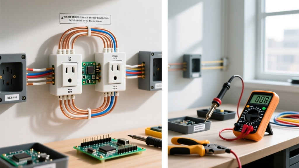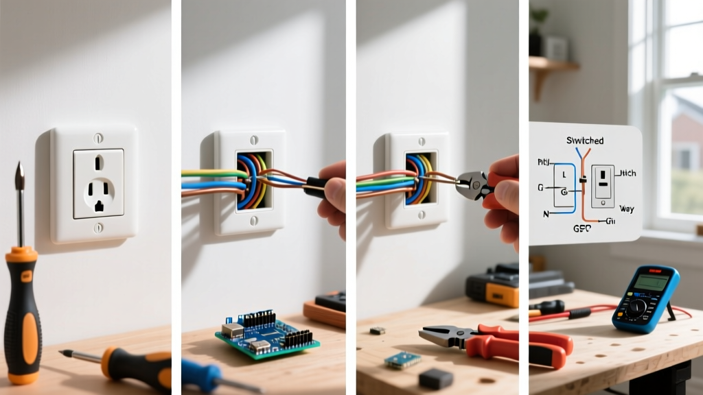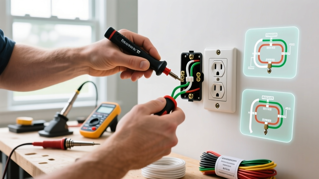

The Hidden Dangers of Aging Receptacles
Knowing how to replace an electrical outlet is a fundamental DIY skill, but treating it as a simple "swap and screw" job ignores critical safety hazards and modern electrical codes. According to the National Fire Protection Association (NFPA), electrical failures or malfunctions are a leading cause of home fires, often originating at degraded receptacle connections. Loose terminal screws, degraded backstab push-in connections, and missing equipment grounds create high-resistance points that generate extreme heat, eventually melting the polycarbonate faceplate and igniting surrounding drywall paper.
When you learn how to replace an electrical outlet correctly, you are not just restoring power to a room; you are bringing an aging circuit up to modern safety standards. This guide focuses strictly on National Electrical Code (NEC) compliance, precise torque specifications, and advanced troubleshooting for edge cases that standard tutorials miss.
NEC Code Requirements for Outlet Replacement
The NEC does not require you to rewire your entire house when replacing a single failed receptacle, but it does mandate specific upgrades based on the existing wiring infrastructure. Under NEC Article 406.4(D), replacement of receptacles must adhere to the following hierarchy:
NEC 406.4(D) Receptacle Replacement Rules:
(1) Grounding Type: Where a grounding means exists in the receptacle enclosure, a grounding-type receptacle must be installed.
(2) Non-Grounding Type (GFCI): Where no grounding means exists, a non-grounding receptacle may be replaced with a GFCI receptacle (marked "No Equipment Ground") or a standard receptacle protected by an upstream GFCI.
(3) Tamper-Resistant (TR): All 15A and 20A, 125V and 250V receptacles installed in dwelling units must be tamper-resistant per NEC 406.12.
The U.S. Consumer Product Safety Commission (CPSC) heavily endorses TR receptacles, noting their internal shutters prevent children from inserting foreign objects into the slots, reducing shock and burn injuries by over 80%.
When to Upgrade from Standard to GFCI or AFCI
If you are replacing an outlet in specific zones, code dictates enhanced protection. Use the matrix below to determine the required receptacle type for your replacement project.
| Location / Circuit Type | Required Protection | NEC Reference | Recommended Device Model |
|---|---|---|---|
| Kitchens, Bathrooms, Garages, Outdoors | GFCI (Ground Fault) | 210.8(A) | Leviton GFNT2-W (20A TR GFCI) |
| Bedrooms, Living Rooms, Hallways | AFCI (Arc Fault) | 210.12 / 406.4(D)(4) | Eaton AFTR15 (15A TR AFCI) |
| Laundry Areas, Wet Bar Sinks (within 6 ft) | GFCI | 210.8(A)(7-10) | Pass & Seymour 2095TRGW |
| Standard Dry Living Areas (No ground wire) | GFCI (Labeled No Eq. Ground) | 406.4(D)(2) | Leviton GFNT2-W with sticker |
Essential Tools & Material Specifications
Professional electricians do not use pocket knives to strip wires or guess terminal tightness. To ensure a fire-safe installation, gather the following specific tools:
- Non-Contact Voltage Tester & Multimeter: Fluke T6-1250 Electrical Tester (~$220) or a budget Klein NCVT-3 (~$35) paired with a standard digital multimeter to verify true zero voltage.
- Precision Wire Strippers: Klein Tools 11055 (10-20 AWG Solid, ~$28). Using the exact gauge hole prevents nicking the copper conductor, which creates a fracture point that snaps under torque.
- Torque Screwdriver: Wiha 28506 Insulated Torque Screwdriver (~$95) or CDI 401SM (~$110). This is non-negotiable for modern code compliance.
- Receptacles: Leviton T5262-E (15A Tamper-Resistant Duplex, ~$2.85 each). Avoid builder-grade $0.60 receptacles; they use thin brass contacts that lose tension after a few plug insertions.
Step-by-Step Replacement: A Code-Compliant Workflow
Follow this exact sequence to ensure your replacement meets 2026 safety standards.
- De-energize and Verify: Turn off the breaker. Insert a multimeter probe into the hot (short) slot and neutral (long) slot. It must read 0.0V. Test hot to ground as well.
- Extract and Inspect: Remove the 6-32 mounting screws. Pull the yoke out gently. Inspect the wire insulation for heat damage (brittle, darkened, or cracked rubber). If the insulation crumbles, you must cut back the wire and use a THHN pigtail inside a wire nut.
- Identify the Circuit Topology: Look for two black and two white wires. This indicates a "daisy chain" (feed and load). Identify the line (power source) and load (downstream) using a tick-tracer or by temporarily energizing the circuit with pigtails safely capped.
- Prepare the Conductors: Strip exactly 3/4 inch of insulation using the 14 AWG solid hole on your Klein 11055. Do not strip more; exposed copper outside the terminal is a shock hazard and a code violation.
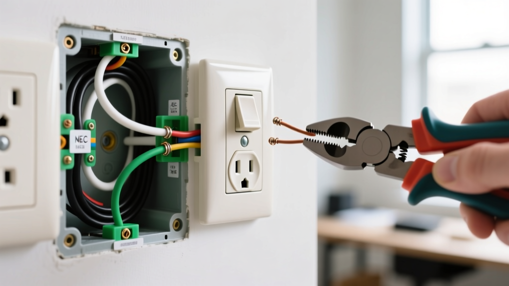
- Form the Hook: Use needle-nose pliers to form a smooth, continuous hook. The hook must travel clockwise around the terminal screw. This ensures that tightening the screw pulls the wire loop tighter rather than pushing it out.
- Terminate and Torque: Place the loop under the screw head, ensuring no insulation is trapped under the screw and no bare copper is exposed outside the yoke. Tighten to the manufacturer's specified torque (see below).
- Wrap and Secure: Wrap the sides of the receptacle with 3/4-inch Scotch 35 electrical tape (or use Leviton SureThread yoke covers) to prevent accidental shorting against grounded metal boxes. Push the wires neatly into the box using the "accordion fold" method, and tighten the 6-32 mounting screws until the plaster ears sit flush against the drywall.
Torque Specifications: The Overlooked Safety Metric
The EC&M National Electrical Code Guide emphasizes that NEC 110.14(D) requires terminations to be torqued to the manufacturer's specifications. Under-torquing causes thermal expansion and contraction cycles to loosen the connection, leading to arcing. Over-torquing strips the screw threads or crushes the copper, reducing the wire's cross-sectional area and increasing resistance.
Standard Leviton 15A/20A Duplex Receptacle Torque Specs:
- 14 AWG Solid Copper: 14 in-lbs (inch-pounds)
- 12 AWG Solid Copper: 16 in-lbs
- 12 AWG Stranded Copper: 14 in-lbs (Must use pin terminals or ferrules; do not loop bare stranded wire directly under a screw head without a pressure plate).
Troubleshooting Common Wiring Edge Cases
When learning how to replace an electrical outlet, you will inevitably encounter non-standard wiring left behind by previous DIYers. Here is how to handle dangerous edge cases:
The "Bootleg" Ground Hazard
In older homes with 2-wire (ungrounded) systems, previous owners sometimes install a 3-prong receptacle by running a jumper wire from the neutral terminal to the ground screw. This is a "bootleg ground." It tricks a standard 3-light tester into reading "Correct," but it is lethal. If the neutral wire ever disconnects upstream, the metal casing of any plugged-in appliance will become energized at 120V. The Fix: Remove the jumper. Install a GFCI receptacle, leave the ground screw empty, and apply the included "No Equipment Ground" sticker to the faceplate.
Multi-Wire Branch Circuits (MWBC)
If you open a box and find a red wire, a black wire, and a shared white neutral, you are dealing with an MWBC. The red and black wires are on two different breaker phases sharing one neutral. Critical Safety Step: If you are replacing a receptacle where the hot-side brass tab is broken off to feed the top and bottom halves from different phases, you must ensure the two breakers are tied together with a listed handle tie (e.g., Eaton HT-1, ~$4) or a 2-pole breaker. If you fail to do this, turning off only one breaker leaves the other half of the receptacle energized, posing a fatal shock risk to anyone working on the downstream circuit.
Backstabbed Push-In Connections
Never use the push-in holes on the back of a receptacle. While technically UL-listed for 14 AWG solid wire, the internal spring-loaded brass grips degrade over time, especially under high continuous loads like space heaters (1500W). Always cut off the backstabbed ends, re-strip the wire, and use the side-terminal screws.
Frequently Asked Questions
Can I replace a 15-amp outlet with a 20-amp outlet?
No. NEC 210.21(B)(3) prohibits installing a 20-amp receptacle (identified by the T-shaped neutral slot) on a 15-amp circuit. The circuit breaker is sized to protect the 14 AWG wire; a 20A receptacle implies to the user that they can safely plug in a 20A load, which could overheat the 14 AWG wiring before the 15A breaker trips. You may, however, install 15A receptacles on a 20A circuit (provided there is more than one receptacle on the circuit).
Do I need to use the pigtailing method for daisy-chained outlets?
While the NEC allows using the receptacle's internal brass tab to pass power downstream (feed-through), best practice for high-load circuits (kitchens, bathrooms) is to pigtail the wires. Pigtailing involves joining the incoming and outgoing wires with a Wago 221 lever nut (~$0.50 each) or a copper crimp sleeve, and running a single pigtail to the receptacle. This ensures that if the receptacle is removed for future servicing, the downstream outlets do not lose power, and it prevents the receptacle's internal brass tab from carrying the full continuous load of downstream devices.
Why is my new TR outlet so hard to plug things into?
Tamper-Resistant (TR) shutters require simultaneous, equal pressure on both internal gates to open. If you push a plug in slightly crooked, one blade hits the shutter before the other, locking the mechanism. The fix is to ensure the plug blades are perfectly straight and to push firmly and squarely. The shutters will loosen slightly after a dozen insertion cycles.