
Understanding the Electrical Outlet Horizontal Configuration
In standard North American residential wiring, duplex receptacles are almost universally mounted vertically, with the ground pin pointing either up or down. However, specific architectural designs, under-cabinet installations, and workbench setups sometimes require mounting an electrical outlet horizontal to the floor or countertop. Rotating a standard NEMA 5-15R or 5-20R receptacle 90 degrees changes the mechanical dynamics of the installation, even though the fundamental electrical circuit remains identical.
This wiring diagram reference explores the National Electrical Code (NEC) compliance, mechanical considerations, and exact wiring procedures for installing a horizontal duplex receptacle in 2026. Whether you are accommodating bulky power adapters or designing a custom workshop, understanding the physical and electrical nuances of this orientation is critical for a safe, long-lasting installation.
NEC Code Compliance and AHJ Preferences
A common question among DIYers and apprentice electricians is whether the NEC explicitly forbids horizontal receptacle mounting. According to NFPA 70 (National Electrical Code), Article 406.5 dictates that receptacles must be mounted in approved boxes and secured tightly. The code does not explicitly mandate a vertical orientation for standard residential duplex receptacles.
Code Insight: While the NEC allows horizontal mounting, the Authority Having Jurisdiction (AHJ) or local inspector may have specific amendments. Furthermore, if the receptacle is installed in a wet location, the orientation must not compromise the weatherproof cover's ability to shed water, as per NEC 406.9.
For hospital-grade or isolated ground receptacles in healthcare facilities, local codes often strictly require the ground pin to point UP to prevent falling debris from shorting across partially exposed prongs. In a horizontal mount, the ground pin points left or right, which largely mitigates the falling debris risk, making it acceptable in most commercial and residential inspections.
Wiring Diagram and Step-by-Step Installation
The electrical connections for an electrical outlet horizontal mount are exactly the same as a vertical mount. The alternating current (AC) waveform does not have a physical 'direction' relative to the wall. However, because horizontal plugs experience different gravitational shear forces, we recommend using back-wired (clamping) or side-wired with a tight J-hook rather than push-in back-stab connections.
Required Tools and Materials
- 15A or 20A Spec-Grade Duplex Receptacle (e.g., Leviton 5262-SW or Hubbell HBL5262, approx. $4.50 - $8.00)
- Single-gang electrical box (Standard depth or extra-deep like Carlon B618R-UPC for $2.15)
- Wire strippers, Lineman pliers, and a calibrated torque screwdriver
- 14 AWG or 12 AWG NM-B (Romex) cable
Wiring Procedure
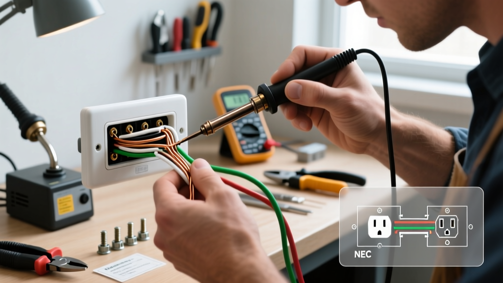
- Prepare the Wires: Strip 3/4 inch of insulation from the black (hot), white (neutral), and bare (ground) wires. If using 12 AWG wire, ensure the receptacle is rated for 12 AWG back-wiring or use a pigtail to 14 AWG for side screws.
- Connect the Ground: Loop the bare copper wire clockwise around the green ground screw. Tighten to 12 in-lbs. The ground screw will now point either left or right.
- Connect the Neutral: Attach the white wire to the silver terminal. If side-wiring, form a tight clockwise J-hook. If back-wiring, insert the straight stripped wire into the clamp hole and tighten the screw until the internal plate locks the wire.
- Connect the Hot: Attach the black wire to the brass terminal using the same method as the neutral.
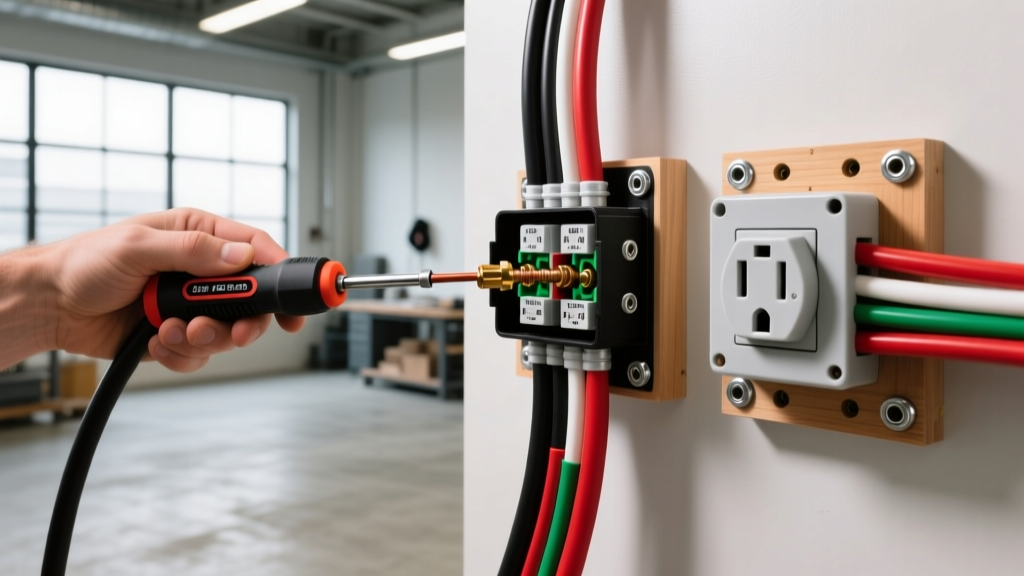
- Physical Mounting: Push the wires neatly into the back of the box. Align the receptacle strap horizontally. Use the mounting screws to secure the strap to the box ears. Pro Tip: If the drywall cutout is slightly oversized, use plastic shims or a receptacle leveling plate (e.g., Caddy TS12, $1.50) behind the strap ears to prevent the outlet from spinning when a plug is inserted or removed.
Mechanical Stress and Box Selection
The primary failure mode of an electrical outlet horizontal installation is mechanical stress on the faceplate and drywall. When a heavy power brick is plugged into a horizontal outlet, gravity pulls the adapter downward, creating a lever effect that can crack standard nylon faceplates or crumble the drywall around the box ears.
| Mounting Orientation | Gravitational Stress on Plug | Recommended Box Type | Best Use Case |
|---|---|---|---|
| Vertical (Standard) | Low (Pulls straight out) | Standard 18 cu in. Single Gang | General room walls, hallways |
| Horizontal (90° Rotation) | High (Downward shear force) | Extra-Deep 22 cu in. Box with Steel Ears | Under-cabinet, workbenches, baseboards |
| Recessed Horizontal | Minimal (Plug sits flush) | Hubbell EB5200 Recessed Box ($16.00) | Behind wall-mounted TVs, large power bricks |
To combat downward shear, always use a high-impact polycarbonate or stainless steel faceplate rather than standard nylon. Additionally, ensure the electrical box is firmly nailed or screwed to a stud. If installing in an old-work (remodel) scenario, use a box with heavy-duty metal flip-clamps (like the Madison Electric Smart Box) rather than plastic wing-clamps, which can slip under lateral torque.
GFCI and Smart Receptacle Considerations
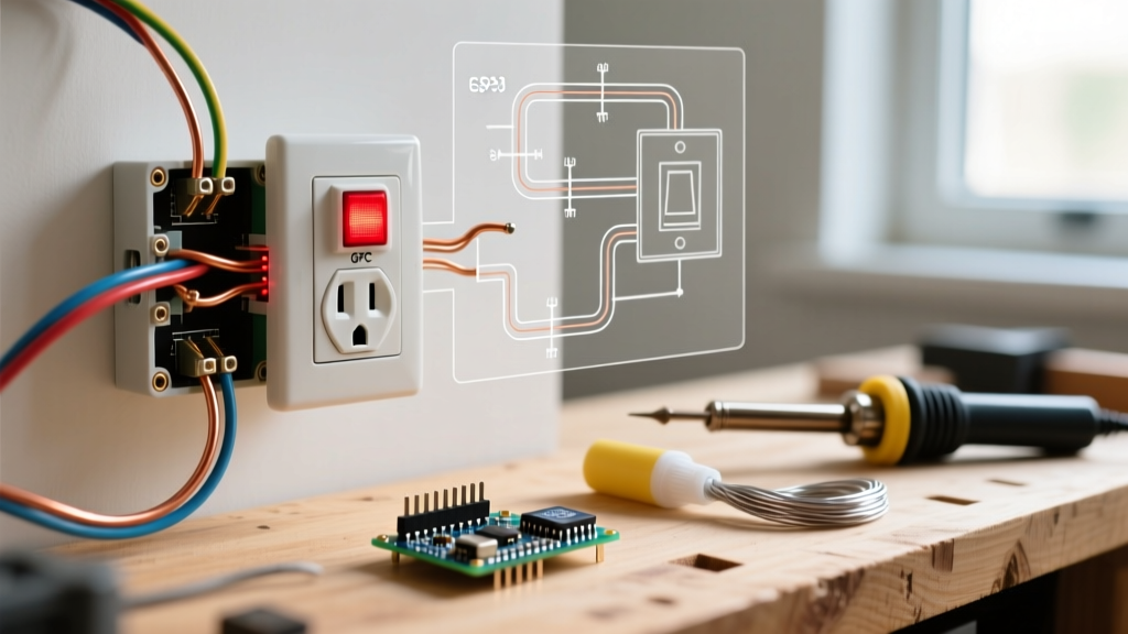
If your local code requires Ground Fault Circuit Interrupter (GFCI) protection for the horizontal outlet (common in kitchens, garages, and workshops), you must consider the internal mechanics of the device. Modern solid-state GFCI receptacles (such as the Pass & Seymour 2095-W or Leviton GFNT1) are orientation-agnostic. The internal sensing toroid and silicon-controlled rectifiers (SCRs) function perfectly regardless of whether the device is mounted vertically, horizontally, or even upside down.
However, physical clearance is a major factor. GFCI and AFCI receptacles are significantly deeper than standard duplex outlets, often requiring 1.25 to 1.5 inches of depth just for the device body. When mounting an electrical outlet horizontal configuration, ensure your wall cavity has no plumbing or blocking directly behind the box that would prevent the deep GFCI body from seating fully. Always use a 22.5 cubic inch deep box for horizontal GFCI installations to allow adequate heat dissipation and wire bending space as mandated by NEC 314.16.
Torque Specifications and Final Inspection
A critical, often overlooked step in both vertical and horizontal receptacle wiring is applying the correct torque to the terminal screws. Loose connections cause arcing, which generates immense heat and is a leading cause of electrical fires. According to OSHA wiring method standards and manufacturer specifications, terminal screws must be tightened to the manufacturer's recommended torque values.
For most spec-grade 15A/20A receptacles manufactured in 2026, the torque requirements are:
- 14 AWG Copper: 12 in-lbs (1.35 Nm)
- 12 AWG Copper: 14 in-lbs (1.58 Nm)
- 10 AWG Copper: 16 in-lbs (1.80 Nm)
Use a calibrated inch-pound torque screwdriver (such as the Klein Tools 60176) to verify these values. This is especially vital for horizontal mounts, where the lateral pull of removing a tight plug can slowly back out an under-torqued screw over several months of use.
Troubleshooting Horizontal Outlet Issues
If you encounter issues after installing a horizontal receptacle, refer to these common edge cases:
- Plug Sagging / Partial Exposure: If the heavy plug sags and exposes the prongs, the drywall behind the faceplate is likely crushed. Remove the faceplate, install a 1/16-inch plastic shim behind the receptacle ears, and replace the faceplate with a mid-size or jumbo polycarbonate cover to bridge the gap.
- Receptacle Spinning in Box: If the outlet rotates when you pull a plug, the plaster ears on the strap are bent, or the box is not flush with the drywall. Break off the plaster ears if they are interfering, and use #6-32 machine screws with a receptacle spacer kit to lock the strap tightly against the box.
- GFCI Tripping on Insertion: If a horizontal GFCI trips the moment a plug is inserted, check for a pinched neutral wire in the back of the box. The tight bending radius of a horizontal mount can sometimes force the bare ground wire to touch the neutral terminal if the wire dress is not meticulously managed.
Authoritative References
For further reading on receptacle installation standards and safety testing, consult the following resources: