
Decoding the Blueprint: How to Repair an Electrical Outlet Safely
Learning how to repair an electrical outlet goes far beyond simply swapping a plastic faceplate. At its core, receptacle repair is an exercise in schematic interpretation. Whether you are troubleshooting a dead kitchen socket, fixing a reversed polarity fault, or upgrading to a tamper-resistant model, referencing the correct wiring diagram is the only way to ensure compliance with the National Electrical Code (NEC) and prevent catastrophic arc faults. According to the U.S. Consumer Product Safety Commission (CPSC), faulty electrical receptacles and improper wiring connections are responsible for over 5,000 residential fires annually. By treating the wiring diagram as your primary diagnostic map, you eliminate guesswork and ensure a secure, code-compliant termination.
Essential Diagnostic Tools & Material Costs (2026 Pricing)
Before consulting a schematic, you must equip yourself with precision tools. Relying on outdated or cheap testers leads to misdiagnosed circuits and severe shock hazards.
- Voltage Tester: Klein Tools NCVT-3 Non-Contact Voltage Tester (Dual-range AC). Retail: $32.00.
- Multimeter: Fluke T6-1000 Electrical Tester (FieldSense technology for open-jaw voltage/current measurement). Retail: $265.00. Budget alternative: Klein MM400 ($48.00).
- Wire Strippers: Klein 11055 (10-20 AWG solid wire). Retail: $28.00.
- Torque Screwdriver: Wiha 28501 Insulated TorqueVario (Required for NEC 110.14(D) compliance). Retail: $95.00.
- Replacement Receptacle: Leviton T5320-W (15A Tamper-Resistant Duplex). Retail: $3.50. For heavy-duty 20A circuits, use the Hubbell 5262 Commercial Grade ($8.50).
Interpreting Standard Receptacle Wiring Diagrams
A standard 120V duplex receptacle wiring diagram maps three distinct conductors to specific terminal nodes. Misinterpreting these nodes is the primary cause of post-repair failures.
The Standard 120V Duplex Schematic
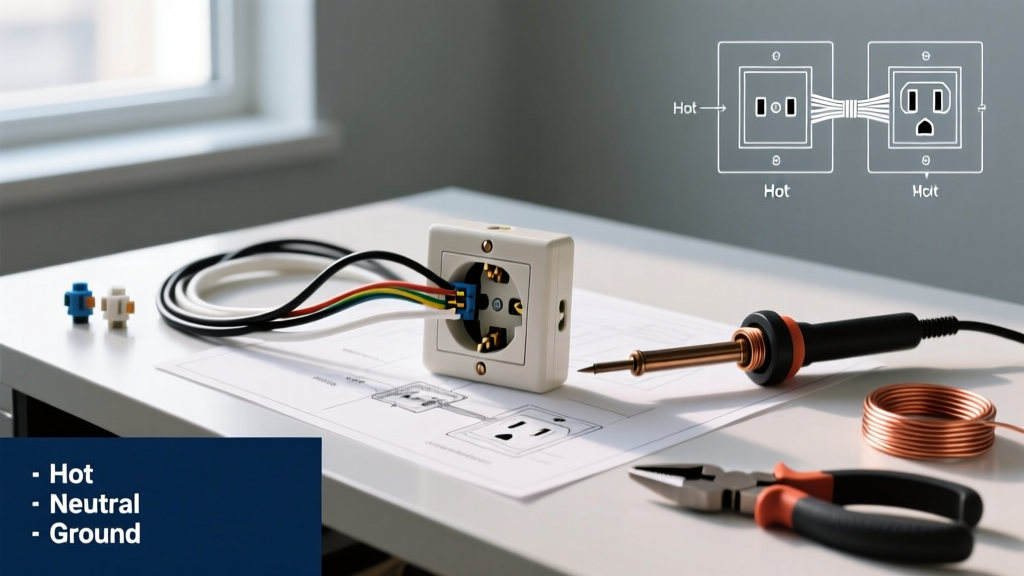
In a basic wiring diagram, the circuit flows from the breaker panel to the outlet's terminal screws. The visual schematic dictates the following color-coded routing:
- Ungrounded Conductor (Hot): Black (or red) insulation routes to the Brass terminal screw.
- Grounded Conductor (Neutral): White (or gray) insulation routes to the Silver terminal screw.
- Equipment Grounding Conductor: Bare copper or green insulation routes to the Green hex-head grounding screw.
Expert Insight: Never use the 'push-in' backstab terminals depicted on the rear of cheap builder-grade receptacles. Wiring diagrams for commercial installations universally specify side-wiring (terminal screw loops) because backstab spring-contacts degrade under thermal expansion, leading to high-resistance open neutrals.
Split-Wired (Half-Switched) Diagram Nuances
A split-wired receptacle diagram is common in living rooms and bedrooms, where the top half is controlled by a wall switch and the bottom half remains constantly hot. The schematic for this configuration reveals a critical physical modification: the brass connecting fin must be broken off. If you are repairing a split outlet and fail to snap the brass tab using needle-nose pliers, closing the wall switch will cause a direct dead short between the two independent hot feeds, instantly tripping the breaker and potentially welding the switch contacts.
Diagnostic Troubleshooting Matrix
When an outlet fails, use this matrix to cross-reference your multimeter readings with the wiring diagram fault points.
| Symptom | Diagram Fault Point | Multimeter Reading (Hot to Neutral) | Corrective Action |
|---|---|---|---|
| Outlet completely dead | Open Hot (Brass terminal) or upstream backstab failure | 0.0V | Trace diagram upstream; re-terminate hot wire on side screw. |
| Reversed Polarity | Black wire on Silver screw; White wire on Brass screw | 120V (but fails NCVT polarity check) | Swap conductors to match standard schematic color codes. |
| Boots on Ground (High Resistance) | Open Ground (Green terminal disconnected) | 120V (Hot-Neutral), 0V (Hot-Ground) | Verify ground wire loop is secured under the green hex screw. |
| Voltage Drop under Load | Loose terminal connection or backstab thermal fatigue | Drops below 110V when vacuum/appliance is turned on | Remove backstabbed wires; form J-hooks and torque to 14 lb-in. |
Step-by-Step Repair Protocol: Executing the Diagram
Follow this precise sequence to execute your wiring diagram repair safely and to modern code standards.
Step 1: De-energize and Lockout
Shut off the branch circuit breaker. Apply a Lockout/Tagout (LOTO) device to the panel to prevent accidental re-energization, a standard practice recommended by the Occupational Safety and Health Administration (OSHA) for all electrical maintenance. Verify the circuit is dead using your NCVT-3 tester on both the top and bottom receptacles.
Step 2: Extract and Inspect the Existing Termination
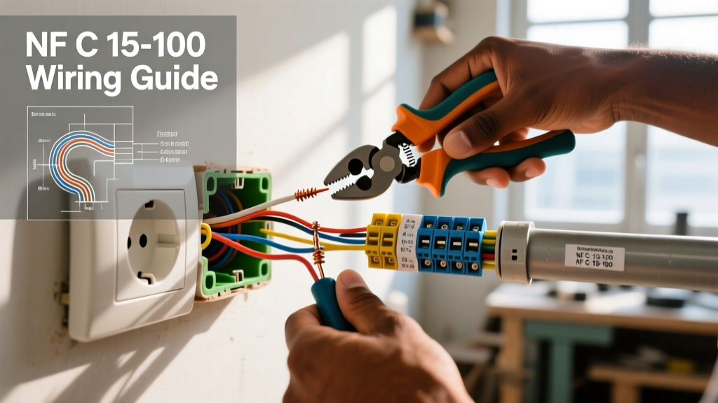
Remove the 6-32 machine screw from the center of the faceplate. Unscrew the top and bottom mounting straps from the junction box. Pull the receptacle out gently. Compare the existing physical wiring to your reference diagram. Look for melted insulation, scorched brass tabs, or copper wire exposed beyond the terminal shoulder (a major shock hazard).
Step 3: Precision Stripping and J-Hook Formation
Cut off any damaged or oxidized wire ends. Using your Klein 11055 strippers, strip exactly 3/4 inch of insulation from 12 AWG or 14 AWG solid copper wire. Using the rounded nose of your pliers, bend the exposed copper into a tight 'J-hook'. The hook must wrap clockwise around the terminal screw. This ensures that as you tighten the screw, the loop pulls tighter rather than splaying outward.
Step 4: Torque to NEC Specifications
The National Fire Protection Association (NFPA 70) strictly mandates that terminal connections be tightened to the manufacturer's specified torque. For standard 15A and 20A Leviton and Hubbell receptacles, this value is typically 14 lb-in (1.6 N·m). Set your Wiha torque screwdriver and tighten until it clicks. Hand-tightening causes micro-arcing and eventual thermal failure.
GFCI Wiring Diagram Nuances: Line vs. Load
Repairing a Ground Fault Circuit Interrupter (GFCI) outlet requires strict adherence to the Line vs. Load schematic. This is where 90% of DIY repairs fail.
- LINE Terminals: These connect directly to the power source (the breaker panel). The incoming hot and neutral must terminate here for the GFCI internal sensing circuitry to power up.
- LOAD Terminals: These feed downstream standard receptacles, extending ground-fault protection to other outlets in the wet area.
Diagnostic Tip: If you repair a GFCI and the 'TEST' button does nothing, or the reset button won't stay engaged, you have likely swapped Line and Load. Use your multimeter to identify the live incoming wires before making connections. Furthermore, ensure the white neutral wires for the Line and Load circuits are not pigtailed together; GFCI diagrams require strict separation of the neutral paths to prevent false tripping.
When to Abort the DIY Repair: If you open the junction box and discover aluminum wiring (typically marked AL or CU-AL on older devices), standard copper-rated receptacles will cause galvanic corrosion and fire. You must use CO/ALR rated receptacles or install Alumiconn pigtails. Additionally, if the wiring diagram reveals a multi-wire branch circuit (MWBC) sharing a neutral without a handle-tied breaker, stop immediately and consult a licensed electrician to bring the panel up to current NEC safety standards.
Final Verification and Energization
Once the physical connections match your wiring diagram and torque specs are verified, carefully fold the wires into the back of the junction box. Push the receptacle flush against the drywall, ensuring the mounting strap sits flat without bowing. Secure with the provided screws, attach the faceplate, and remove your LOTO device. Finally, use a commercial receptacle tester (like the Gardner Bender GFI-3501) to verify correct wiring, proper grounding, and functional GFCI tripping before plugging in any appliances.