
The Definitive Inspection Guide for Single-Pole Light Switches
When troubleshooting residential lighting circuits, the single-pole switch is the most common point of failure. Whether you are dealing with a flickering fixture, a completely dead circuit, or an intermittent connection, a systematic approach to testing is mandatory. Inspecting a basic electrical wiring light switch setup requires moving beyond simple visual checks and utilizing diagnostic tools to verify voltage, continuity, and mechanical integrity. According to the National Fire Protection Association (NFPA), electrical failures or malfunctions are a leading cause of home structure fires, making rigorous inspection protocols critical for both safety and functionality.
This guide provides a comprehensive, step-by-step framework for inspecting and testing standard 15-amp and 20-amp single-pole light switches. We will cover de-energized mechanical inspections, live voltage verification, and continuity testing, equipping you with the exact data points needed to isolate faults.
Essential Diagnostic Tools and Safety Gear
Before opening any junction box, you must assemble the correct diagnostic equipment. Relying on cheap, uncalibrated testers can lead to false readings and severe shock hazards.
- True RMS Digital Multimeter: The Fluke 117 True RMS Multimeter (approx. $195) is the industry standard. It features VoltAlert non-contact voltage detection and a low-impedance (LoZ) mode to eliminate phantom voltage readings.
- Non-Contact Voltage Tester (NCVT): The Klein Tools NCVT-3 (approx. $35) provides dual-range detection (12V to 1000V AC) for initial box verification.
- Torque Screwdriver: A calibrated driver like the Klein Tools 32500, set to 12-14 inch-pounds, ensures terminal screws meet manufacturer specifications.
- Wire Stripper/Crimper: For re-terminating damaged conductors (e.g., Klein Tools 11055 for 10-22 AWG).
- PPE: ASTM-rated insulated gloves and safety glasses, as mandated by OSHA electrical safety standards.
CRITICAL SAFETY WARNING: Never assume a circuit is dead based solely on the switch position or a wall plate label. Always verify the absence of voltage at the termination points using a live-dead-live testing sequence with a calibrated multimeter before touching any bare copper.
Phase 1: Visual and Mechanical Inspection (De-Energized)
Once you have shut off the breaker and verified zero voltage, remove the switch from the junction box. Do not disconnect the wires yet. The initial visual inspection often reveals the root cause of the failure without requiring further electrical testing.
1. Inspect Termination Methods
The most prevalent failure mode in modern basic electrical wiring light switch installations is the use of "backstab" (push-in) connectors. While UL-listed, these spring-loaded internal tangs are highly susceptible to thermal expansion and contraction. Over years of cycling high-wattage incandescent or halogen loads, the heat degrades the spring tension, leading to micro-arcing and eventual open circuits.
- Actionable Fix: If the switch utilizes backstabbed 14 AWG or 12 AWG wires, release the wires using a small flathead screwdriver in the release slot. Strip 3/4 inch of fresh insulation and terminate the wires under the side terminal screws.
2. Verify Torque and Conductor Wrapping
According to NEC Article 110.3(B), equipment must be installed per the manufacturer's instructions. Most switch manufacturers require terminal screws to be tightened to 12-14 inch-pounds.
- Wire Hook Orientation: Ensure the wire loop wraps clockwise around the terminal screw. When the screw is tightened, the loop should close tighter. A counter-clockwise wrap will push the wire out from under the screw head as it is tightened.
- Insulation Clearance: There should be no bare copper exposed outside the terminal saddle (a shock hazard), nor should the wire insulation be pinched under the screw head (which causes a high-resistance connection).
Phase 2: Live Voltage Verification (Energized)
If the visual inspection yields no obvious defects, you must test the circuit under load. Turn the breaker back on. Exercise extreme caution.
1. Line-to-Ground and Line-to-Neutral Testing
Set your multimeter to V AC (or LoZ V AC if you suspect phantom voltage). Identify the "Line" (hot) wire, which is typically the black wire bringing power from the panel, and the "Load" wire, which carries power to the fixture.
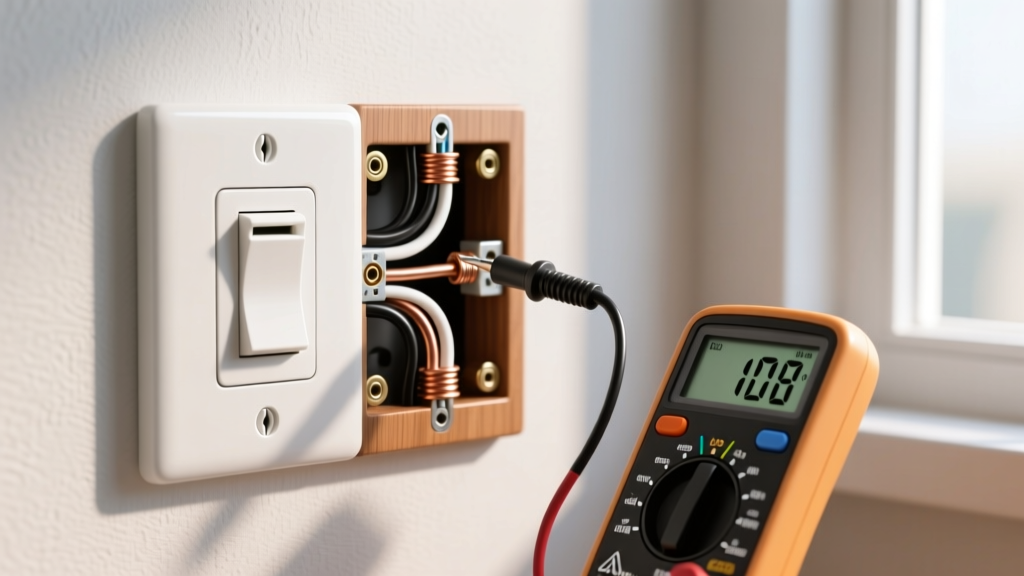
- Place the black probe on the Line terminal screw and the red probe on the bare copper ground wire (or metal box). You should read between 115V and 125V.
- Place the black probe on the Line terminal and the red probe on the bundled neutral wires in the back of the box. You should read the same 115V-125V.
- Diagnostic Insight: If you read 0V Line-to-Ground but 120V Line-to-Neutral, you have an open or missing equipment grounding conductor. This is a severe safety violation that prevents breakers from tripping during a ground fault.
2. Testing the Load Side (Switch ON)
Toggle the switch to the ON position. Measure from the Load terminal screw to the ground wire. You should now read the full source voltage (115V-125V). If the voltage drops significantly (e.g., to 90V or 100V) when the switch is ON and the light fixture is illuminated, you have a high-resistance connection somewhere in the circuit, likely at a wire nut splice in the ceiling canopy or a degraded switch contact.
Phase 3: Continuity and Switch Integrity Testing
If the switch receives voltage but fails to pass it, or if you are testing a newly purchased switch before installation, perform a continuity test. Ensure the breaker is OFF and verified dead before proceeding.
- Set the multimeter to the Continuity setting (the symbol resembling a sound wave).
- Disconnect the Line and Load wires from the switch terminals.
- Place one probe on the Line terminal screw and the other on the Load terminal screw.
- Toggle the switch. In the ON position, the multimeter should beep, and the resistance should read less than 1.0 ohm. In the OFF position, the display should read "OL" (Open Loop) or infinite resistance.
Edge Case: If the multimeter shows fluctuating resistance (e.g., jumping from 0.5 ohms to 15 ohms) while the switch is held firmly in the ON position, the internal brass contact arm is pitted or carbonized. The switch must be replaced immediately.
Diagnostic Matrix: Basic Electrical Wiring Light Switch Faults
| Symptom | Multimeter Reading (Switch ON) | Probable Root Cause | Corrective Action |
|---|---|---|---|
| Light flickers when switch is bumped | Fluctuating voltage (0V to 120V) | Loose terminal screw or failed backstab connection | Re-terminate using side screws; torque to 14 in-lbs |
| Light is dim; switch feels warm | Voltage drop across switch (e.g., 10V) | Internal contact pitting / high resistance | Replace switch (upgrade to 20A spec-grade if load is high) |
| Light works, but NCVT beeps on ground wire | 120V Line-to-Ground, 0V Neutral-to-Ground | Induced phantom voltage or bootleg ground | Use LoZ multimeter mode; verify ground path to panel |
| Breaker trips instantly upon turning switch ON | N/A (Cannot sustain voltage) | Short circuit in Load wire or fixture | Isolate fixture; test Load wire continuity to ground |
Advanced Troubleshooting: Switched Neutrals and Code Violations
One of the most dangerous wiring errors encountered in older homes is the "switched neutral." In this scenario, the basic electrical wiring light switch is wired to interrupt the neutral (white) wire instead of the ungrounded hot (black) wire. NEC Article 404.2(B) explicitly prohibits single-pole switches from disconnecting the neutral conductor.
Why is this dangerous? If a switch interrupts the neutral, the light fixture remains fully energized at 120V even when the switch is in the OFF position. A homeowner attempting to change a lightbulb or perform fixture maintenance will receive a lethal shock if they touch the hot socket contacts and a grounded surface.
How to test for a switched neutral:
- Turn the switch OFF.
- Measure from the Load terminal screw to a known ground. If you read 120V with the switch OFF, the switch is incorrectly wired on the neutral leg.
- Measure from the light fixture's socket shell (the threaded metal part) to ground. It should read 0V. If it reads 120V, the hot and neutral are reversed at the fixture.
For comprehensive guidelines on identifying and mitigating residential wiring hazards, refer to the Consumer Product Safety Commission (CPSC) Electrical Safety Center.
Summary and Final Verification
Properly inspecting a basic electrical wiring light switch requires a methodical progression from visual assessment to live electrical testing. By utilizing a True RMS multimeter, verifying torque specifications, and strictly adhering to NEC polarity requirements, you can eliminate intermittent faults and ensure long-term circuit reliability. Always replace standard residential switches with commercial-grade (spec-grade) models, such as the Leviton 15AC5 or Hubbell HBL5262, which feature deeper wire saddles, thicker brass contact arms, and superior thermal resistance for less than $5 per unit. This minor investment drastically reduces the likelihood of future thermal degradation and mechanical failure.