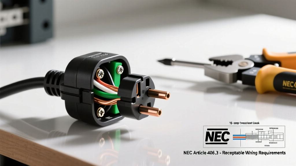

The Reality of Receptacle Wiring in 2026
Hooking up electrical outlet configurations is one of the most common DIY electrical tasks, yet it remains a leading source of residential electrical fires when executed improperly. According to the U.S. Consumer Product Safety Commission (CPSC), electrical receptacles and switches are involved in thousands of home fires annually, often due to loose connections, reversed polarity, or overloaded circuits. As the National Electrical Code (NEC) continues to evolve through its 2023 and 2026 cycles, the requirements for arc-fault (AFCI) and ground-fault (GFCI) protection have become stricter, making proper installation more critical than ever.
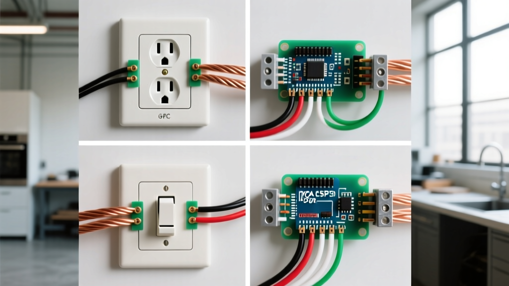
Whether you are replacing a damaged duplex receptacle or wiring a new kitchen branch circuit, understanding the specific wiring scenario is paramount. Below, we break down the four most common scenarios you will encounter when hooking up electrical outlet devices, complete with exact product recommendations, NEC code references, and professional installation techniques.
Scenario 1: The Standard 15A or 20A Duplex Receptacle (End-of-Run)
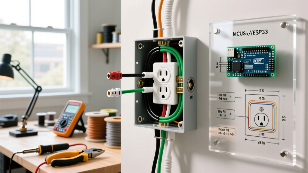
The most basic scenario is wiring a standard receptacle at the end of a branch circuit (end-of-run). Here, only one set of cables enters the electrical box. For general living areas, bedrooms, and hallways, you will typically use a 15-amp circuit with 14 AWG copper wire and a 15A receptacle, such as the Leviton T5262 (retailing around $2.50). For heavier loads or dining rooms, a 20-amp circuit with 12 AWG wire and a 20A receptacle like the Leviton T5266 (approx. $4.00) is required.
Pro-Terminal Connections: Ditch the Backstabs
Amateur electricians often use the push-in 'backstab' holes on the back of cheap receptacles. These spring-loaded connections are notorious for loosening over time due to thermal cycling (the heating and cooling of the wire as current flows). This loosening increases resistance, generating excess heat and creating a fire hazard.
- Side-Wiring (Screw Terminal): Wrap the stripped wire 2/3 of the way around the terminal screw clockwise. Tighten to the manufacturer's specified torque.
- Back-Wiring (Screw-Clamp): Found on commercial-grade receptacles (like the Leviton ProGrade line). You insert the straight stripped wire into a hole, and tightening the screw clamps a heavy-duty brass plate down on the wire. This is the preferred method for maximum surface contact and pull-out resistance.
Scenario 2: GFCI Protection (Line vs. Load Configuration)
Ground Fault Circuit Interrupter (GFCI) receptacles are mandated by the NEC in all wet or damp locations, including bathrooms, kitchens, garages, and outdoor patios. The Leviton GFNT1-W (approx. $18.00) is a staple 15A GFCI. The most common point of failure when hooking up electrical outlet GFCI devices is confusing the LINE and LOAD terminals.
NEC Code Note: Per NFPA 70 (National Electrical Code) Article 406.4(D)(4), replacements in areas requiring GFCI protection must be GFCI-protected, even if no equipment grounding conductor is present in the box (though specific labeling is required in ungrounded scenarios).
Step-by-Step GFCI Wiring Flow
- Identify the Source: Use a non-contact voltage tester to identify the incoming hot wire. This connects to the LINE brass terminal.
- Connect the Neutral: The incoming white neutral wire connects to the LINE silver terminal.
- Determine Downstream Needs: If you need to protect additional outlets down the circuit, connect the outgoing black and white wires to the LOAD terminals. If this is the last outlet, or you only want to protect this single location, cap the LOAD wires with wire nuts and leave the LOAD terminals empty.
- Grounding: Connect the bare copper or green wire to the green grounding screw. If the box is metal, a pigtail must also connect the box to the ground wire.
Scenario 3: The Switched Half-Receptacle (Split-Tab)
In many living rooms and bedrooms, building codes require a switched receptacle so occupants can control a floor lamp via a wall switch. This is achieved using a split-tab duplex receptacle. The top half is controlled by the wall switch, while the bottom half remains constantly hot for devices like phone chargers or vacuums.
Breaking the Fin and Wiring the Split
To create this setup, you must use a receptacle with a breakable brass connecting fin on the hot side. Using a pair of lineman's pliers, bend the brass tab back and forth until it snaps off. Do not break the silver tab on the neutral side.
- Constant Hot (Black Wire): Connects to one of the brass screws (usually the bottom).
- Switched Hot (Red Wire): Connects to the other brass screw (usually the top). This wire runs back to the wall switch.
- Neutral (White Wire): Connects to the silver screw.
- Ground (Bare Wire): Connects to the green screw.
This scenario requires a 3-wire cable (14/3 or 12/3 Romex) running from the switch to the receptacle box to accommodate the constant hot, the switched hot, the shared neutral, and the ground.
Scenario 4: 20A Kitchen Small Appliance Branch Circuit
Kitchens demand dedicated 20-amp Small Appliance Branch Circuits (SABCs) to handle high-draw devices like microwaves, toasters, and air fryers. NEC Article 210.52(B) requires at least two 20A circuits for kitchen countertop receptacles. When hooking up electrical outlet devices in a kitchen, you must use 12 AWG copper wire and a 20-amp rated receptacle.
Identifying a 20A Receptacle
A true 20A receptacle (like the Hubbell HBL5262) features a unique T-shaped neutral slot. This allows it to accept both standard 15A plugs (which are far more common on kitchen appliances) and specialized 20A NEMA 5-20P plugs found on heavy-duty commercial equipment. While the NEC permits 15A receptacles on a 20A circuit (provided there are multiple receptacles on the yoke), installing a 20A receptacle provides maximum durability and ensures the internal contacts are rated for the full 20-amp continuous load without thermal degradation.
Wire, Breaker, and Receptacle Compatibility Matrix
Mismatching wire gauge, breaker size, and receptacle ratings is a severe code violation that can lead to melted insulation and electrical fires. Use the table below as a quick reference guide before starting your project.
| Breaker Size | Minimum Wire Gauge (Copper) | Receptacle Rating | Typical Application |
|---|---|---|---|
| 15 Amp | 14 AWG | 15 Amp | Bedrooms, Living Rooms, Hallways |
| 20 Amp | 12 AWG | 15A or 20A | Kitchen Countertops, Bathrooms, Garages |
| 30 Amp | 10 AWG | 30 Amp (Specialty) | Dryers, RV Hookups (Not standard duplex) |
The Overlooked Code Requirement: Torque Specifications
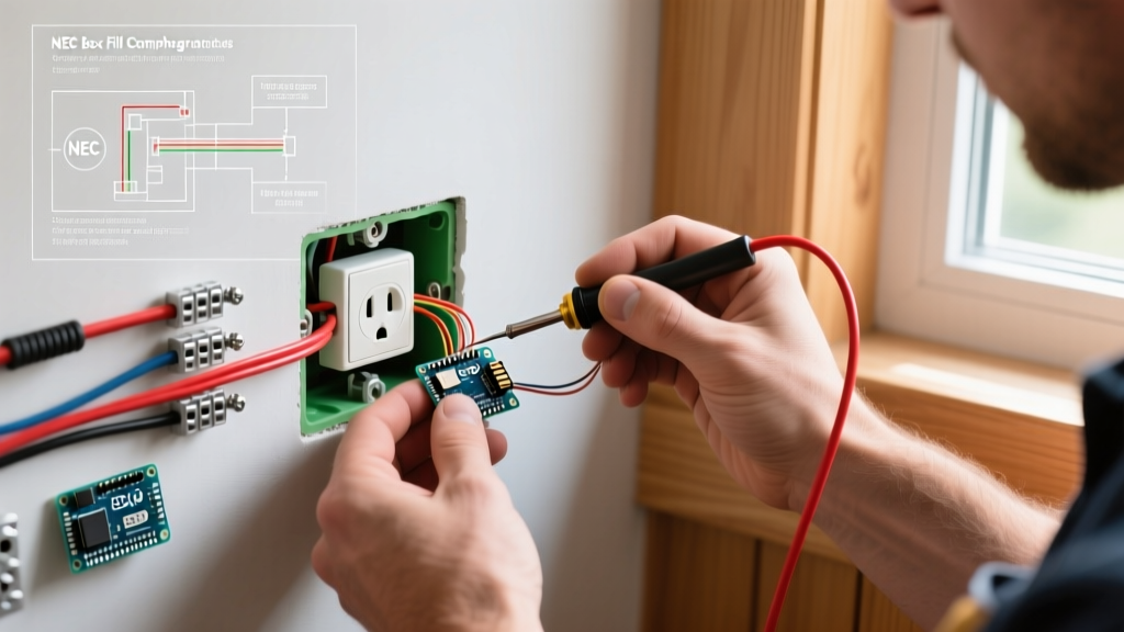
One of the most significant updates in recent NEC cycles (specifically NEC 110.14(D)) is the mandate for using calibrated torque tools when terminating electrical connections. Guessing how tight a terminal screw should be is no longer acceptable or safe. Under-torqued screws cause arcing; over-torqued screws strip threads or shear the wire strands.
For standard 15A and 20A receptacles terminating 14 AWG to 10 AWG solid copper wire, the typical torque specification ranges from 12 to 16 inch-pounds. Professional electricians use tools like the Milwaukee 48-22-7105 torque screwdriver (approx. $130) to ensure every terminal is tightened exactly to the manufacturer's specifications printed on the back of the device.
Troubleshooting Common Failure Modes
Even with careful installation, issues can arise. Here is how to diagnose the three most common failure modes when testing your newly installed receptacle with a standard 3-light circuit tester:
- Open Ground: The tester shows a yellow light on the right only. This means the equipment grounding conductor is disconnected or broken. Fix: Check the ground wire connection at the receptacle and trace it back to the panel. Ensure metal boxes are properly bonded.
- Reversed Polarity: The tester shows a yellow light on the left only. The hot and neutral wires are swapped. Fix: Turn off the breaker, verify that the black wire is on the brass screw and the white wire is on the silver screw. This is a severe shock hazard.
- Hot/Ground Reverse: The tester shows red and yellow lights. This is highly dangerous and usually indicates a miswired circuit where the ground is carrying current. Fix: Immediately shut off the breaker and re-verify all connections in the box and the upstream junction boxes.
Final Safety Reminders
Before hooking up electrical outlet devices, always verify the circuit is de-energized using a trusted dual-range voltage tester (like the Fluke 2AC-II VoltAlert) at the wires themselves, not just by assuming the breaker label is correct. Furthermore, ensure your workspace complies with OSHA electrical safety guidelines, keeping the area dry and using insulated tools. By respecting the physics of electrical resistance and adhering strictly to NEC code requirements, you ensure a safe, reliable, and long-lasting installation.