
The Definitive Reference for Electrical Receptacle Wiring
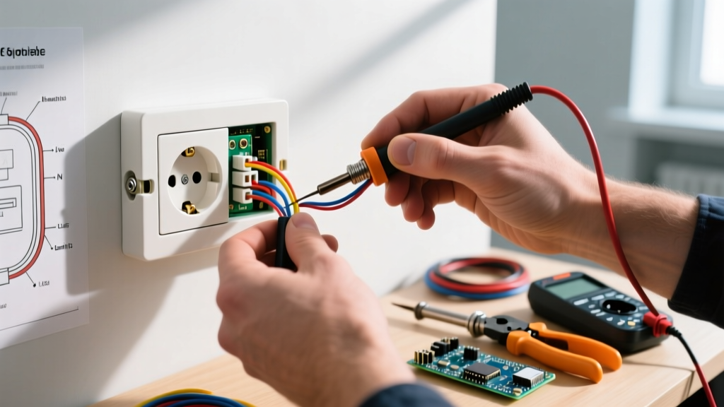
Proper electrical receptacle wiring is the foundation of a safe, code-compliant residential electrical system. Whether you are upgrading a 1970s ungrounded circuit to a modern 20A tamper-resistant setup or troubleshooting a tripped GFCI, understanding the exact terminal configurations, wire gauges, and National Electrical Code (NEC) requirements is non-negotiable. This reference guide bypasses generic advice, providing exact wiring diagrams, torque specifications, and edge-case troubleshooting for standard, GFCI, and multi-wire branch circuit (MWBC) receptacles.
Receptacle Anatomy and Terminal Identification
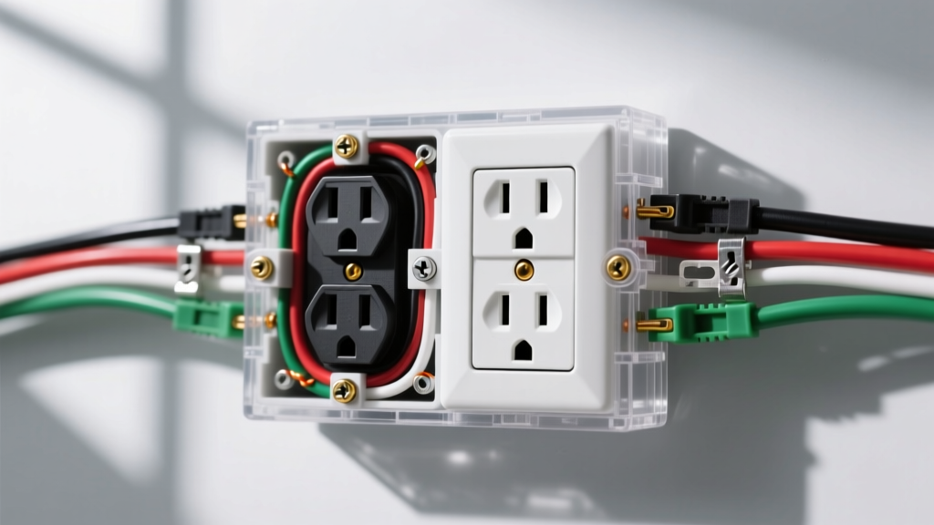
Before executing any electrical receptacle wiring, you must understand the physical anatomy of a standard NEMA 5-15R or 5-20R duplex receptacle. Modern devices, such as the Leviton T5262 or Hubbell 5262, feature three distinct terminal sets:
- Brass Screws (Hot): Connects to the black (or red) ungrounded conductor. The tab between the two brass screws can be broken off to create a split-receptacle circuit.
- Silver Screws (Neutral): Connects to the white grounded conductor. The tab between the silver screws should never be broken in standard residential wiring.
- Green Screw (Ground): Connects to the bare copper or green insulated equipment grounding conductor (EGC).
Expert Warning: Never use the "backstab" push-in terminals found on contractor-grade receptacles. They rely on a spring-loaded friction grip that degrades under thermal cycling, leading to high-resistance arcing faults. Always use side-wiring or screw-and-clamp terminals, wrapping the wire clockwise around the screw or inserting it under the clamp plate.
Standard 15A vs. 20A Wiring Specifications
The most common error in electrical receptacle wiring is mismatching the breaker size, wire gauge, and receptacle rating. The NEC strictly dictates these pairings to prevent conductor overheating.
| Specification | 15A Circuit (NEMA 5-15R) | 20A Circuit (NEMA 5-20R) |
|---|---|---|
| Minimum Wire Gauge | 14 AWG Copper (12 AWG permitted) | 12 AWG Copper (Strict) |
| Breaker Size | 15 Amp Single-Pole | 20 Amp Single-Pole |
| Receptacle Rating | 15A or 20A Feed-Through | 20A Rated Only |
| Terminal Torque Spec | 14 in-lbs (1.59 N-m) | 14 in-lbs (1.59 N-m) |
| Primary NEC Application | Bedrooms, Living Rooms, Hallways | Kitchens, Bathrooms, Garages, Outdoors |
Step-by-Step Standard Wiring Flow
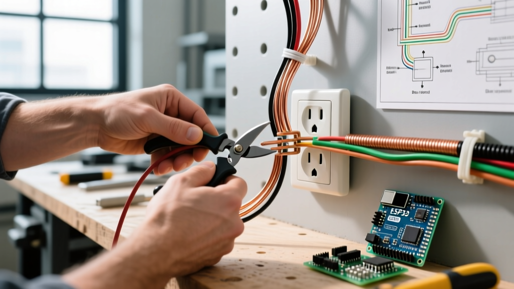
- Strip the Wire: Remove exactly 3/4 inch of insulation. Exposing too much bare wire creates a shock hazard; too little causes the screw to bite into the insulation, resulting in an open circuit.
- Form the J-Hook: Use needle-nose pliers to form a tight hook. Loop it clockwise so tightening the screw pulls the wire tighter rather than pushing it out.
- Torque to Spec: Use a calibrated torque screwdriver (e.g., Klein Tools 70005) set to 14 in-lbs. Under-torqued connections are the leading cause of residential electrical fires due to thermal expansion and contraction loosening the screw over time.
GFCI Receptacle Wiring: Line vs. Load Mastery
Ground Fault Circuit Interrupter (GFCI) wiring introduces a critical variable: downstream protection. According to the Consumer Product Safety Commission (CPSC), GFCIs prevent over 300 electrocutions annually by detecting current imbalances as small as 4 to 6 milliamps and tripping in under 25 milliseconds.
The Line vs. Load Distinction
A GFCI receptacle (like the Leviton GFNL1-W) has two sets of terminals clearly marked on the back:
- LINE Terminals: These connect to the incoming power source from the breaker panel. If you only need to protect the single outlet, you only wire the LINE terminals and cap the LOAD wires with wire nuts.
- LOAD Terminals: These feed power to downstream standard receptacles. Wiring a downstream outlet to the LOAD terminals extends GFCI protection to those devices.
If you accidentally wire the incoming power to the LOAD terminals and the downstream outlets to the LINE terminals, the GFCI will still power the receptacle and pass a standard plug-in tester. However, the internal sensing coil is bypassed, meaning it will not trip during a ground fault, leaving the user completely unprotected. Always verify incoming power with a non-contact voltage tester before connecting to the LINE terminals.
Multi-Wire Branch Circuits (MWBC) and Split Receptacles
In kitchen and dining room applications, electrical receptacle wiring often utilizes a Multi-Wire Branch Circuit to double the available power without running new cable. An MWBC uses a 3-wire cable (Black, Red, White, Bare) sharing a single neutral conductor.
Wiring a Split Receptacle for an MWBC
- Break the Hot Tab: Use lineman's pliers to snap off the brass connecting tab on the side of the receptacle. Leave the silver (neutral) tab intact.
- Connect the Hots: Wire the Black (Hot 1) to the top brass screw, and the Red (Hot 2) to the bottom brass screw.
- Connect Neutral and Ground: Wire the White neutral to the silver screw and the bare copper to the green ground screw.
NEC 2023/2026 Compliance Note: Under NFPA 70 (NEC) Article 210.4(B), all ungrounded conductors of an MWBC must be provided with a means to disconnect simultaneously. This requires either a 2-pole breaker or two single-pole breakers with an identified handle tie. Furthermore, the neutral wire must be pigtailed at the receptacle; you cannot use the receptacle's internal silver strap as the neutral path, as removing the device would open the neutral for the active circuit, potentially sending 240V across 120V appliances.
Advanced Troubleshooting Matrix
When electrical receptacle wiring fails validation via a standard 3-light tester (e.g., Gardner Bender GFI-3501), use this diagnostic matrix to identify the root cause before opening the junction box.
| Tester Indication | Probable Wiring Fault | Corrective Action |
|---|---|---|
| Open Neutral | Loose silver screw, broken neutral tab, or failed backstab connection upstream. | Check upstream receptacles for push-in failures; re-terminate neutral with side-wiring and torque to 14 in-lbs. |
| Hot/Neutral Reversed | Black wire on silver screw, white wire on brass screw. | Swap conductors. Ensure the narrower slot (hot) aligns with the brass terminal. |
| Hot/Ground Reversed | Bootleg ground or accidental cross-termination of bare copper to brass terminal. | Verify ground continuity to the panel ground bus. Remove any jumper wires between neutral and ground. |
| Open Ground | Missing EGC, loose green screw, or broken ground wire in the cable sheath. | If no ground exists in the box, NEC Article 210.8 allows replacing with a GFCI receptacle marked "No Equipment Ground". |
Safety and Code Adherence
Electrical receptacle wiring is not merely about making a connection; it is about ensuring long-term thermal stability and fault-clearing capability. Always verify that the circuit is de-energized using a CAT III or CAT IV rated multimeter before touching any terminals. For comprehensive safety protocols regarding lockout/tagout and wiring methods, refer to the Occupational Safety and Health Administration (OSHA) electrical safety guidelines.
By adhering to exact torque specifications, eliminating backstab connections, and properly configuring Line/Load and MWBC pigtails, you ensure your receptacle wiring will pass inspection and operate safely for decades.