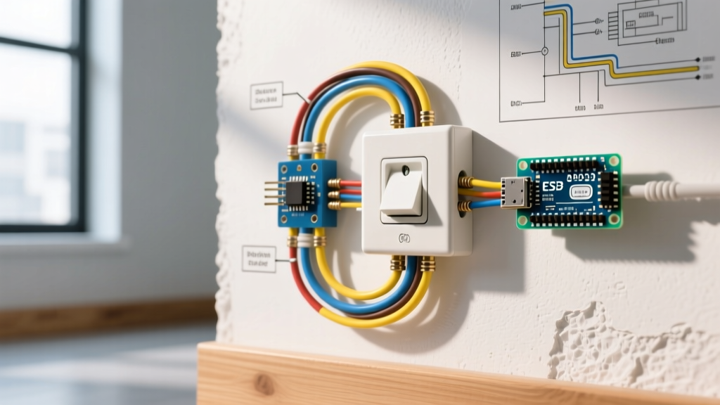

Bridging the Terminology Gap: Socket vs. Receptacle
Expert Note: While the National Electrical Code (NEC) officially classifies wall plugs as receptacles and light bulb holders as sockets, the term electrical outlet socket is universally used by homeowners to describe the standard 120V AC wall receptacle. This inspection guide bridges professional NEC terminology with practical home diagnostics to ensure you are testing the exact right component.
An electrical outlet socket is the most frequently interacted-with component in any residential wiring system. Yet, it is also the most prone to hidden degradation. By 2026, with the increased adoption of high-draw smart home hubs, EV charging adapters, and advanced power conditioning systems, the thermal and electrical stress on standard 15A and 20A receptacles has never been higher. A simple visual check is no longer sufficient. This comprehensive inspection and testing guide will walk you through professional-grade diagnostics to uncover hidden wiring faults, voltage drops, and dangerous code violations.
Essential Diagnostic Arsenal for 2026
Before opening a single faceplate, you need the right tools. Relying on guesswork or non-contact voltage pens is insufficient for true circuit analysis.
- Advanced GFCI/Receptacle Tester: The Klein Tools RT250 (approx. $35) is an industry standard. Unlike basic 3-light testers, it features an LCD screen that explicitly identifies wiring faults and tests GFCI trip circuits without relying on ambiguous light combinations.
- True-RMS Digital Multimeter: The Fluke 117 Electricians True-RMS Multimeter (approx. $200) is critical for measuring exact voltage drops and identifying phantom voltages caused by induced currents in parallel wiring.
- Thermal Imaging Camera: The FLIR C5 (approx. $550) allows you to scan the faceplate for thermal anomalies indicating high-resistance connections behind the wall before you even touch a screwdriver.
- Torque Screwdriver: Following recent NEC mandates, the Klein 69001 (approx. $60) ensures terminal screws are tightened to the manufacturer's exact specification, preventing arc faults.
Phase 1: Visual and Thermal Inspection
Before inserting any probes, conduct a non-invasive inspection of the electrical outlet socket.
Thermal Scanning
With a standard load plugged into the receptacle (such as a 1500W space heater or a heavy-duty work light), scan the faceplate with a thermal camera. A temperature differential (ΔT) of more than 15°C (27°F) between the receptacle slots and the ambient wall temperature indicates a high-resistance connection, usually caused by failing internal brass contacts or loose backstabbed wiring.
The 'Backstab' Push-In Fitting Check
Remove the faceplate and inspect the side of the receptacle body. If you see stripped 14 AWG or 12 AWG copper wires pushed into the small holes on the back (push-in or 'backstab' fittings), mark this receptacle for immediate replacement. Push-in fittings rely on a tiny internal spring that loses tension over time, especially under thermal cycling, leading to arcing. According to the U.S. Consumer Product Safety Commission (CPSC), loose connections are a primary catalyst for residential electrical fires.
Phase 2: Plug-In Tester Analysis and Limitations
Insert your receptacle tester into the electrical outlet socket. While LCD testers provide text readouts, traditional 3-light testers use a specific matrix of neon lamps. Below is the standard diagnostic matrix for a 3-light tester:
| Light Pattern (Left to Right) | Condition | Required Action |
|---|---|---|
| Off - Yellow - Yellow | Correct Wiring | Proceed to voltage verification. |
| Off - Yellow - Off | Open Ground | Verify ground wire continuity to panel. |
| Off - Off - Yellow | Open Neutral | Check neutral bus bar and pigtail connections. |
| Yellow - Off - Off | Hot/Neutral Reversed | Swap brass (hot) and silver (neutral) wires. |
| Yellow - Yellow - Off | Hot/Ground Reversed | Dangerous. Panel miswire suspected. Call an electrician. |
The Blind Spot: Bootleg Grounds
A standard plug-in tester has a fatal flaw: it cannot detect a 'bootleg ground.' This occurs when a previous DIYer or unscrupulous handyman connects a jumper wire between the neutral terminal and the ground screw on the receptacle to trick a tester into showing a 'correct' ground. If a fault occurs, the equipment grounding path becomes energized, posing a lethal shock hazard. To catch this, you must proceed to Phase 3.
Phase 3: Multimeter Voltage Verification
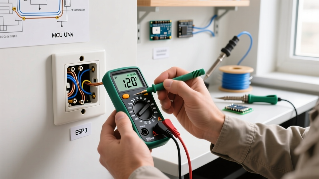
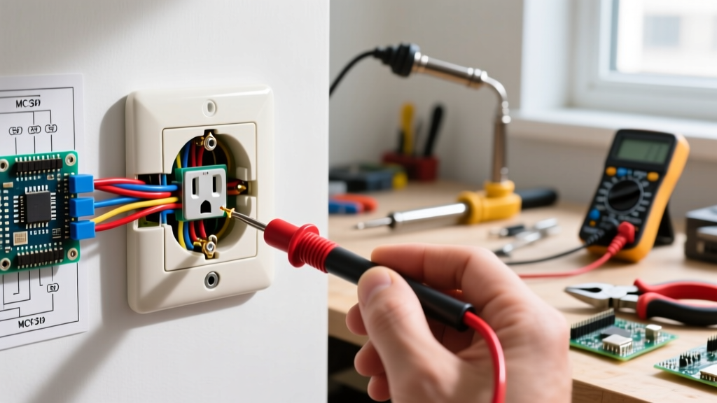
Set your True-RMS multimeter to AC Voltage (V~). You will take three distinct measurements at the electrical outlet socket. According to ANSI C84.1 standards, standard US residential voltage should be maintained between 114V and 126V.
Step-by-Step Measurement Protocol
- Line to Neutral (Hot to Neutral): Insert the red probe into the shorter (hot) slot and the black probe into the longer (neutral) slot. Expected Reading: 114V - 126V. If it reads below 110V, you have a voltage drop issue, likely caused by an overloaded circuit or undersized wire on a long run.
- Line to Ground (Hot to Ground): Insert the red probe into the hot slot and the black probe into the round ground hole. Expected Reading: Within 1V of your L-N reading. If this reads 0V while L-N reads 120V, you have an open ground (or a bootleg ground that has failed).
- Neutral to Ground: Insert the red probe into the neutral slot and the black probe into the ground hole. Expected Reading: Less than 2V (ideally < 0.5V). If this reads 3V or higher, it indicates a loose neutral connection somewhere upstream, or a shared neutral circuit that is severely overloaded. This is a critical fire hazard that requires immediate panel inspection.
Phase 4: GFCI and AFCI Trip Testing
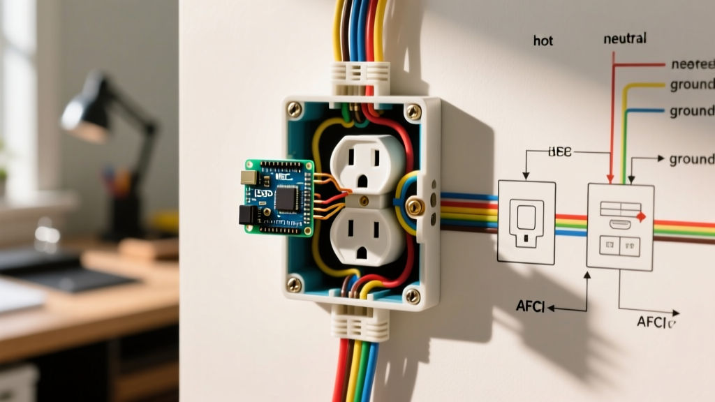
Modern electrical codes require Ground Fault Circuit Interrupter (GFCI) protection in wet areas and Arc Fault Circuit Interrupter (AFCI) protection in living spaces. The National Fire Protection Association (NFPA) continually updates these requirements to mitigate shock and fire risks.
To test a GFCI electrical outlet socket, plug in your tester and press the black 'Test' button. The receptacle should physically click and cut power within 25 milliseconds. If it does not trip, or if it trips but still registers voltage on your multimeter, the internal solenoid has failed and the device must be replaced immediately. Note that GFCI receptacles have a finite lifespan of roughly 10 years; if your home was wired in 2015, it is time to proactively replace them.
Torque Specifications and Reassembly
If your testing reveals loose wires requiring re-termination, do not simply tighten them by feel. The NEC now strictly requires the use of a calibrated torque screwdriver for terminal connections. For a standard 15A Leviton or Eaton receptacle, the manufacturer typically specifies a torque of 14 in-lbs for the terminal screws. Over-tightening can strip the brass threads or damage the wire, while under-tightening leads to thermal expansion gaps and arcing. Furthermore, always use the side-screw terminals or the screw-clamp plates, never the backstab holes.
Summary of Edge Cases
- Phantom Voltage: If your multimeter reads 40V-70V on a dead circuit, switch to a low-impedance (LoZ) setting if your meter supports it. This eliminates ghost voltages induced by parallel live wires in the same wall cavity.
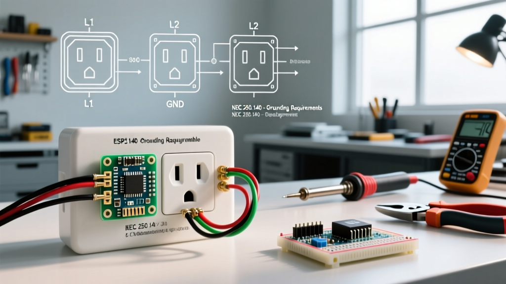
- Multi-Wire Branch Circuits (MWBC): If you find two hot wires (one black, one red) connected to a single duplex receptacle, ensure the metal break-off tab on the hot side has been removed. Failing to do so creates a dead short across 240V, resulting in an immediate and violent breaker trip.
By systematically applying visual, thermal, and multimeter diagnostics, you move beyond basic troubleshooting and perform true electrical system verification. For broader home electrical safety guidelines and panel maintenance, consult resources provided by the U.S. Department of Energy. Always turn off the circuit breaker at the main panel and verify zero energy before removing any receptacle from the junction box.