
The Case for Upgrading to a 6-Pin Trailer System
Transitioning from a standard 4-way flat connector to a 6-way round connector is one of the most impactful electrical upgrades you can make to your towing setup. While a 4-pin system handles basic illumination (tail, brake, and turn signals), it completely lacks the circuitry required for electric trailer brakes and 12V auxiliary power. As of 2026, with modern proportional brake controllers like the Curt Spectrum (Model 51170) becoming the industry baseline for safe towing, relying on a 4-pin adapter is no longer sufficient for trailers exceeding 3,000 lbs GVWR.
This comprehensive upgrade guide and wiring diagram for a 6 pin trailer plug provides the exact specifications, wire gauge requirements, and physical installation protocols needed to replace a damaged connector or upgrade an older chassis. Proper execution ensures compliance with federal lighting standards and eliminates the voltage drop issues that plague poorly wired aftermarket setups.
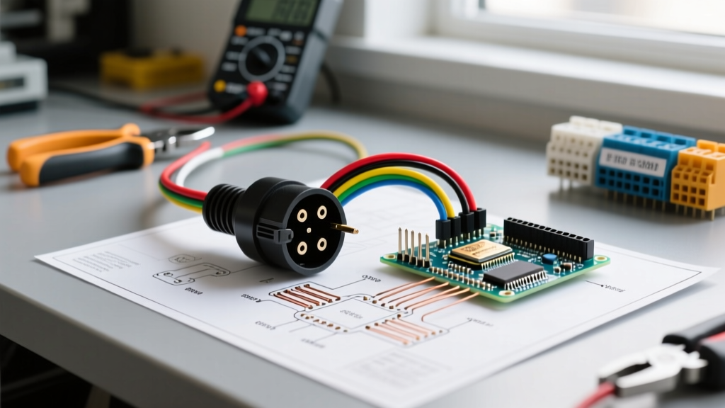
Official Wiring Diagram for a 6 Pin Trailer Plug (RV Standard)
The 6-way round connector (often referred to as the RV standard) utilizes a specific clock-face pinout. The most common industry-standard replacement connectors, such as the Pollak 11-726 or Curt 58260, follow the exact matrix detailed below. Note that the center pin is exclusively reserved for 12V auxiliary power, while the bottom pin handles the high-amperage electric brake circuit.
| Pin Position | Function | Standard Wire Color | Minimum Wire Gauge | Circuit Amperage |
|---|---|---|---|---|
| 10 o'clock (Top Left) | Ground (System) | White | 12 AWG | N/A (Return Path) |
| 2 o'clock (Top Right) | Tail / Running Lights | Brown | 16 AWG | 5A - 10A |
| 5 o'clock (Bottom Left) | Left Turn / Stop | Yellow | 16 AWG | 5A - 10A |
| 7 o'clock (Bottom Right) | Right Turn / Stop | Green | 16 AWG | 5A - 10A |
| 6 o'clock (Bottom Center) | Electric Brakes | Blue | 12 AWG | 10A - 15A |
| Center Pin | 12V Auxiliary Power | Black (or Red) | 12 AWG | 15A - 30A |
Reference: For federal compliance regarding commercial and heavy-duty trailer lighting circuits, consult the Federal Motor Carrier Safety Administration (FMCSA) Appendix G inspection standards.
Critical Engineering: Wire Sizing and Voltage Drop
The most common failure point in a 6-pin trailer upgrade is undersizing the blue (brake) and white (ground) wires. Many DIYers use 16 AWG wire for all six circuits to save money. This is a critical engineering error. The SAE International J1128 Standard for low-tension primary cable dictates that high-draw circuits require thicker conductors to prevent resistive heating and voltage drop.
The Voltage Drop Calculation
Consider a standard 20-foot run from the tow vehicle's brake controller to the trailer's axle brakes, drawing 12 amps during a hard braking event:
- Using 16 AWG Copper: Resistance is roughly 4.016 ohms per 1,000 ft. Over a 40-foot round trip (20 ft positive, 20 ft ground), the voltage drop is approximately 1.92V. Your 12V controller outputs 12V, but the brakes only receive 10.08V, resulting in weak braking and potential controller error codes.
- Using 12 AWG Copper: Resistance drops to 1.588 ohms per 1,000 ft. The voltage drop over the same 40-foot round trip is only 0.76V. The brakes receive 11.24V, ensuring immediate, forceful actuation.
Always purchase SAE J1128 compliant stranded copper wire. Avoid Copper-Clad Aluminum (CCA) wires sold in cheap 2026 marketplace kits, as they suffer from 30% higher resistance and severe galvanic corrosion when exposed to road salt.
Step-by-Step Replacement & Upgrade Protocol
Whether you are cutting off a melted 4-pin flat or replacing a corroded 6-pin round, follow this exact protocol to ensure a weather-tight, vibration-resistant connection.
1. Chassis Preparation and Routing
- Disconnect Power: Disconnect the negative terminal on the tow vehicle and trailer batteries before splicing.
- Route the Loom: Feed a 1/2-inch split-loom tubing through the trailer tongue. Secure it every 18 inches using UV-resistant zip ties and self-tapping screws with nylon lock nuts to prevent chassis vibration from tearing the wires.
- Strip and Prep: Strip exactly 5/16-inch of insulation from the end of each wire. Do not nick the copper strands; a compromised strand creates a localized hot spot under high amperage.
2. Crimping and Weatherproofing
Do not use solder on trailer plug connections. Solder is brittle and will fracture under the constant harmonic vibration of highway towing. Instead, use a ratcheting crimper (such as the Titan 19470) with closed-barrel, adhesive-lined heat shrink terminals.
- Slide a piece of 3M 3/16-inch adhesive-lined heat shrink tubing over the wire before crimping.
- Insert the stripped wire into the terminal barrel until it hits the internal stop.
- Crimp using the correct die (usually marked '12-10' or '16-14' AWG). The ratchet must release only when full compression is achieved.
- Apply heat at 250°F until the adhesive sealant purges slightly from the edges of the tubing, creating a 100% waterproof seal.
3. Terminal Insertion and Dielectric Grease
Insert the crimped terminals into the rear of the Pollak or Curt connector housing. Ensure the locking tab clicks into place. Before mating the plug to the socket, pack the interior cavity with Permatex 22058 Dielectric Tune-Up Grease. This displaces moisture and prevents the copper and brass terminals from galvanic corrosion, which is the primary cause of the 'ghost lighting' phenomenon where turn signals bleed into the brake circuits.
Common Failure Modes and Edge Cases
Even with a perfect wiring diagram for a 6 pin trailer plug, real-world conditions introduce edge cases that can derail your upgrade.
Expert Insight: Never rely on the trailer chassis as your primary ground return path. The white 12 AWG ground wire must run continuously from the 6-pin plug directly to the trailer's main ground bus bar, and ideally back to the tow vehicle's battery negative. Chassis grounding through the hitch ball is highly unreliable due to paint, rust, and articulation movement, leading to flickering lights and brake controller dropouts.
Troubleshooting the 'Weak Brakes' Edge Case
If your brake controller (e.g., Redarc Tow-Pro Elite or Curt Spectrum) shows a full 10.0V output on its digital display, but the trailer brakes feel sluggish, the issue is almost always a voltage drop on the blue wire or a poor ground on the white wire. Use a digital multimeter to measure voltage directly at the trailer axle's brake magnet while a helper applies the manual override slider in the cab. If the voltage at the magnet is more than 1.5V lower than the controller's output, you must upsize your blue and white wires to 10 AWG.
Auxiliary Power Circuit Overloads
The center pin (Black/Red) provides 12V auxiliary power, often used to charge a trailer breakaway battery or power interior RV lights. In 2026, with the rise of high-draw 12V compressor fridges and lithium battery chargers in overland trailers, this circuit is easily overloaded. Standard 12 AWG wire on a 30A breaker will melt if a continuous 25A load is applied over a long wire run. If your auxiliary draw exceeds 15A continuous, upgrade the center pin wire to 10 AWG and install a dedicated 30A marine-grade circuit breaker within 18 inches of the tow vehicle's battery positive terminal.
Frequently Asked Questions (FAQ)
Can I use a 6-pin to 4-pin adapter instead of rewiring?
You can use an adapter (like the Curt 47435) for basic lighting, but an adapter physically cannot transmit the electric brake signal or auxiliary power. If your trailer has electric brakes, an adapter is illegal and highly dangerous, as it leaves the trailer without independent stopping power.
Why are my trailer running lights blowing fuses immediately after the upgrade?
This indicates a dead short on the brown wire circuit. During the upgrade, the brown wire was likely pinched between the trailer tongue and the steel frame, or the tail light housing was improperly grounded, causing the 12V positive to arc directly to the chassis. Inspect all brown wire routing points and ensure tail light housings are isolated or properly grounded to the dedicated white wire bus.
What is the difference between a 6-pin round and a 6-pin square connector?
The 6-pin round (RV style) is the modern standard for medium-duty towing. The 6-pin square (often found on older Jayco or vintage trailers) uses a completely different pinout and physical housing. They are not interchangeable. If you are upgrading a vintage trailer, it is highly recommended to cut off the square plug and wire in a modern 6-pin round plug to ensure compatibility with modern tow vehicles. For more historical wiring context, refer to the Curt Manufacturing Towing Guides.