
Beyond the Basics: The Inspection-Driven Approach to Outlet Installation
When DIYers and apprentice electricians search for instructions on how to put an electrical outlet, the results usually focus on the physical act of stripping wires and wrapping them around brass terminal screws. However, at ElectricalFlux, we know that passing a municipal inspection and ensuring long-term fire safety requires a much more rigorous methodology. As municipalities accelerate their adoption of the latest NEC (National Electrical Code) cycles leading into 2026, inspectors are cracking down on improper box fill, un-torqued terminals, and missing AFCI/GFCI protections.
This guide shifts the focus from basic wiring to the critical inspection and testing protocols that separate a hazardous hack-job from a master-level installation. Whether you are retrofitting a receptacle into an existing drywall surface or roughing-in a new branch circuit, this is your definitive testing matrix.
Phase 1: Pre-Rough-In Inspection & Box Fill Calculations
Before you even think about terminating a wire, you must inspect the electrical box itself. The most common reason for a failed rough-in inspection is violating NEC Article 314 regarding box fill. Overcrowded boxes trap heat, degrading wire insulation over time and creating a severe fire hazard.
Calculating Volume Allowances
To determine if your box is legally sized, you must calculate the total number of "conductor equivalents" inside the box and multiply that by the volume allowance for your specific wire gauge. According to the NFPA 70 (NEC) Table 314.16(B), the volume allowances are strictly defined.
| Conductor Size | Volume Allowance per Conductor | Typical Application |
|---|---|---|
| 14 AWG | 2.0 cubic inches | 15-Amp Lighting & Receptacle Circuits |
| 12 AWG | 2.25 cubic inches | 20-Amp Kitchen, Bathroom, & Garage Circuits |
| 10 AWG | 2.5 cubic inches | 30-Amp Dryer or HVAC Equipment |
The Box Fill Math (Real-World Scenario)
Imagine you are installing a standard 12/2 NM-B (Romex) cable into a single-gang box to feed a 20A receptacle, and another 12/2 cable leaving the box to daisy-chain to the next outlet. Here is how an inspector counts the fill:
- Hot Wires: 2 entering/leaving (Count: 2)
- Neutral Wires: 2 entering/leaving (Count: 2)
- Ground Wires: All bare grounds count as a single 12 AWG equivalent (Count: 1)
- Internal Clamps: If using metal boxes with internal clamps, count as 1 (Count: 1)
- The Device (Receptacle):strong> The yoke counts as 2 conductor equivalents (Count: 2)
Total Count: 8 equivalents.
Required Volume: 8 x 2.25 cu in = 18.0 cubic inches minimum.
If you attempt to stuff this into a standard 14 cu. in. "old work" box (like the Carlon B114R), you will fail inspection. You must upgrade to a deep box, such as the Carlon B120R (20 cu. in.).
Phase 2: Cable Securing and Routing Inspection
Inspectors will physically tug on your cables during the rough-in phase. Per NEC 300.11 and 334.30, nonmetallic-sheathed cable must be secured and supported. When putting an electrical outlet into an existing wall where you cannot easily staple the stud, the code provides a specific exception: the cable must be secured within 8 inches of the single-gang box. If you are using a retrofit "old work" box without internal cable clamps, you must use a listed cable clamp (like the Raco 931) at the knockout to secure the wire, otherwise, the physical strain will eventually pull the hot wire off the terminal screw.
Expert Insight: Never rely on the friction of the drywall to hold an old-work box in place. Always torque the box's mounting wings until they are fully flush and tight against the back of the drywall. A loose box will eventually push into the wall cavity when a user unplugs a stiff cord, exposing live terminals.
Phase 3: Termination and Torque Verification
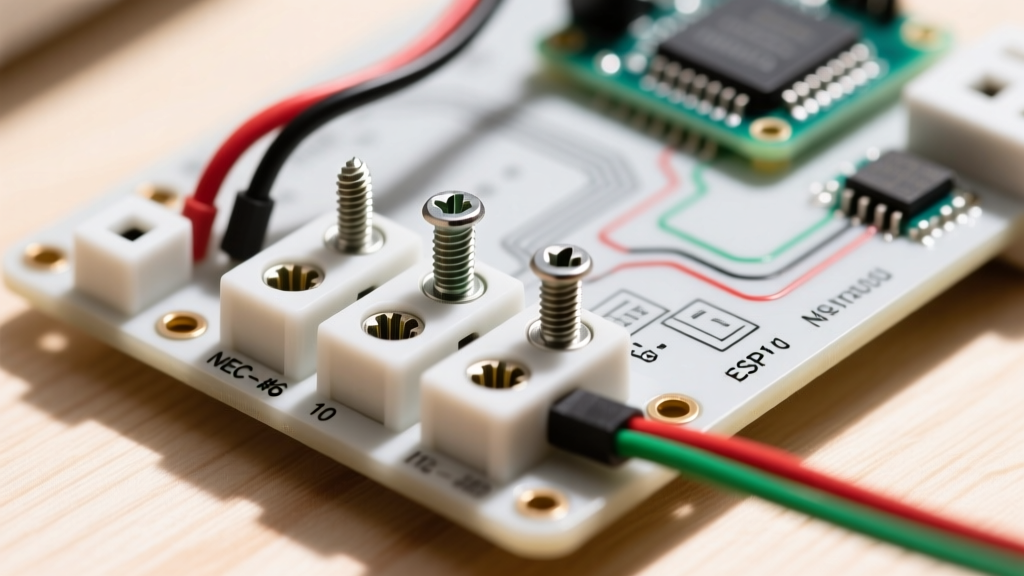
The physical act of attaching the wire to the receptacle is where most electrical fires originate. Modern electrical codes (specifically NEC 110.14(D)) now strictly mandate that terminations be torqued to the manufacturer's specified values using a calibrated torque tool.
Why Hand-Tightening is No Longer Acceptable
Copper and aluminum undergo "cold flow" and thermal expansion. If you under-torque a terminal screw, the connection loosens over time, increasing resistance and generating massive heat. If you over-torque it, you strip the threads or crush the wire strands, reducing the cross-sectional area and creating a bottleneck for current.
For standard 15A and 20A Leviton or Hubbell commercial-grade receptacles, the manufacturer specifies a torque of 14 inch-pounds (in-lbs) for 12 AWG and 14 AWG solid copper wire on the brass and silver terminal screws. You must use a specialized torque screwdriver, such as the Wiha 64500 or Klein Tools 69010, to verify this. Furthermore, always use the "shepherd's hook" method, wrapping the wire clockwise around the screw so that tightening the screw pulls the loop tighter, rather than pushing it out.
Phase 4: Post-Installation Testing Protocol
Once the drywall is finished, the cover plate is on, and the breaker is energized, the testing phase begins. Do not rely solely on a cheap $10 plug-in receptacle tester. While useful for a quick sanity check, they cannot identify high-resistance grounds or bootleg grounds.
Step 1: True-RMS Voltage Verification
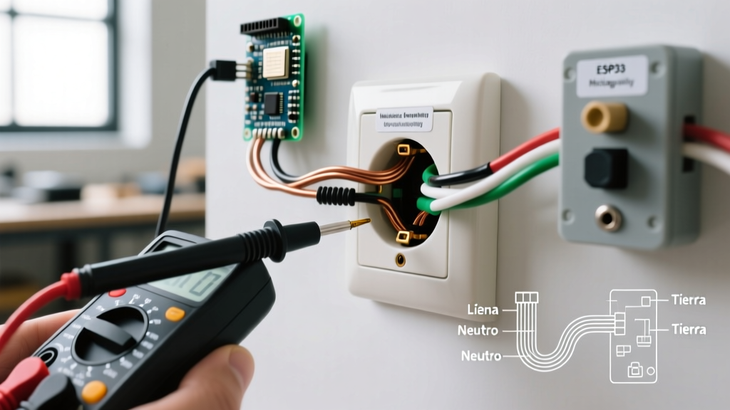
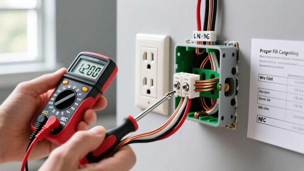
Using a True-RMS digital multimeter (such as the Fluke 117), perform a three-point voltage test:
- Hot to Neutral: Should read 118V - 122V.
- Hot to Ground: Should read identical to Hot-Neutral (within 0.5V).
- Neutral to Ground: Should read less than 2V. (A reading higher than 2V indicates a voltage drop on the neutral wire, meaning the circuit is overloaded or the neutral connection is loose somewhere upstream).
Step 2: GFCI and AFCI Functional Testing
If you are putting an electrical outlet in a kitchen, bathroom, garage, or outdoor location, it must be GFCI protected. According to the U.S. Consumer Product Safety Commission (CPSC), GFCI protection is non-negotiable for preventing fatal electrocution in damp environments.
Use a dedicated GFCI tester with a high-impedance trip circuit, like the Amprobe GFI-350A. Plug it in and press the black test button. The receptacle should trip instantly (within 20-30 milliseconds). If you are testing a downstream receptacle that is protected by an upstream GFCI, the upstream GFCI must trip. If it does not, your Line and Load wires are reversed at the source GFCI.
Advanced Troubleshooting Matrix
When a standard 3-light receptacle tester shows a fault, novice electricians often misdiagnose the issue. Below is an advanced troubleshooting matrix to help you identify the true root cause of the fault, accounting for dangerous edge cases like "bootleg" grounds.
| Tester Light Pattern | Standard Indication | Advanced Diagnostic Step & Real Root Cause |
|---|---|---|
| Yellow / Yellow / Off | Open Ground | Verify with a multimeter (Hot to Ground). If you read 120V, you have a "bootleg ground" (a jumper wire between neutral and ground). This is highly dangerous and must be removed immediately. |
| Off / Yellow / Yellow | Open Neutral | Check the neutral bus bar in the main panel. Often caused by a pushed-in backstab connection on an upstream receptacle that has vibrated loose. |
| Yellow / Off / Yellow | Hot/Neutral Reversed | Check the breaker panel. The white neutral wire may have been incorrectly landed on the hot bus bar, or the black/white wires were swapped at the receptacle yoke. |
| Off / Off / Yellow | Hot/Equip Ground Reversed | Extremely rare and dangerous. The bare ground wire is energized. Turn off the main breaker immediately and trace the cable for a short circuit. |
Safety and Compliance Final Thoughts
Understanding how to put an electrical outlet is fundamentally about understanding the flow of current and the mechanical integrity of the connections. As electrical loads in modern homes continue to rise with the integration of smart home hubs, EV chargers, and high-draw appliances, the margin for error shrinks. Always adhere to OSHA electrical safety guidelines regarding lockout/tagout (LOTO) procedures before opening any panel or junction box. By combining rigorous box-fill math, precise torque specifications, and advanced multimeter testing, you ensure your installation is not just functional, but fundamentally safe and inspection-ready for decades to come.