
Why Your Outside Electrical Outlet Stopped Working: A Wiring Diagram Approach
When an exterior receptacle loses power, the issue rarely lies in a simple tripped breaker. Modern outdoor circuits are complex daisy-chains of Ground Fault Circuit Interrupters (GFCIs), weather-resistant (WR) components, and buried UF-B cabling. If your outside electrical outlet stopped working, diagnosing the failure requires understanding the underlying wiring diagram and how current flows from your main panel to the exterior wall.
According to the National Fire Protection Association (NFPA), all 15- and 20-amp, 125-volt outdoor receptacles must be GFCI protected. This means your dead outdoor outlet is likely downstream of an indoor GFCI (often located in a garage, bathroom, or basement) or is a WR GFCI itself that has failed internally due to moisture ingress. This guide provides a structural wiring diagram reference to isolate the fault, test the circuit paths, and restore power safely.
The Anatomy of an Outdoor Receptacle Circuit
Before grabbing a screwdriver, you must map the circuit topology. Exterior outlets are typically wired in one of two configurations:
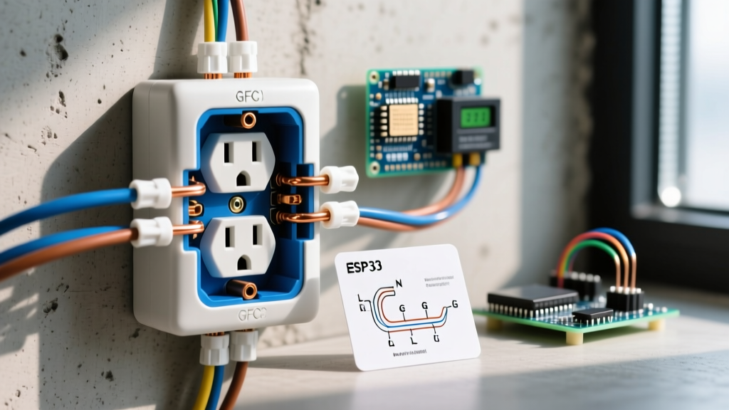
- Downstream Protection (Feed-Through): Power runs from the breaker panel to an indoor GFCI receptacle. The LOAD terminals of that indoor GFCI feed a standard 12/2 or 14/2 NM-B cable through the wall cavity to the exterior WR receptacle. If the indoor GFCI trips, the outside electrical outlet stopped working immediately.
- Point-of-Use Protection: A standard breaker feeds power directly to an outdoor Weather-Resistant (WR) GFCI receptacle. The GFCI electronics are housed inside the weatherproof exterior box. These are highly susceptible to UV degradation and thermal cycling.
Diagnostic Troubleshooting Matrix
Use this matrix to cross-reference your physical symptoms with the likely wiring diagram failure points.
| Symptom | Multimeter Reading (Hot-to-Neutral) | Probable Wiring Diagram Fault | Required Fix |
|---|---|---|---|
| Outlet completely dead, no reset button on face | 0.0V | Upstream indoor GFCI tripped or open neutral on LOAD terminals. | Locate upstream GFCI, reset. Check LOAD wire nut connections. |
| Outlet dead, exterior GFCI button won't stay depressed | N/A (Mechanical failure) | Internal GFCI relay corroded or moisture breached the WR housing. | Replace with Leviton 5280-WMP or equivalent WR GFCI. |
| Devices plug in but immediately lose power under load | 120V (No load), drops to <10V under load | Backstabbed push-in connections failed; high resistance joint. | Move wires to terminal screws, torque to 14 in-lbs. |
| Phantom voltage detected, tools won't power on | 40V - 70V (High impedance) | Induced ghost voltage from parallel runs; open hot conductor. | Test with LoZ multimeter setting; trace broken hot wire. |
Step-by-Step Multimeter Diagnostics
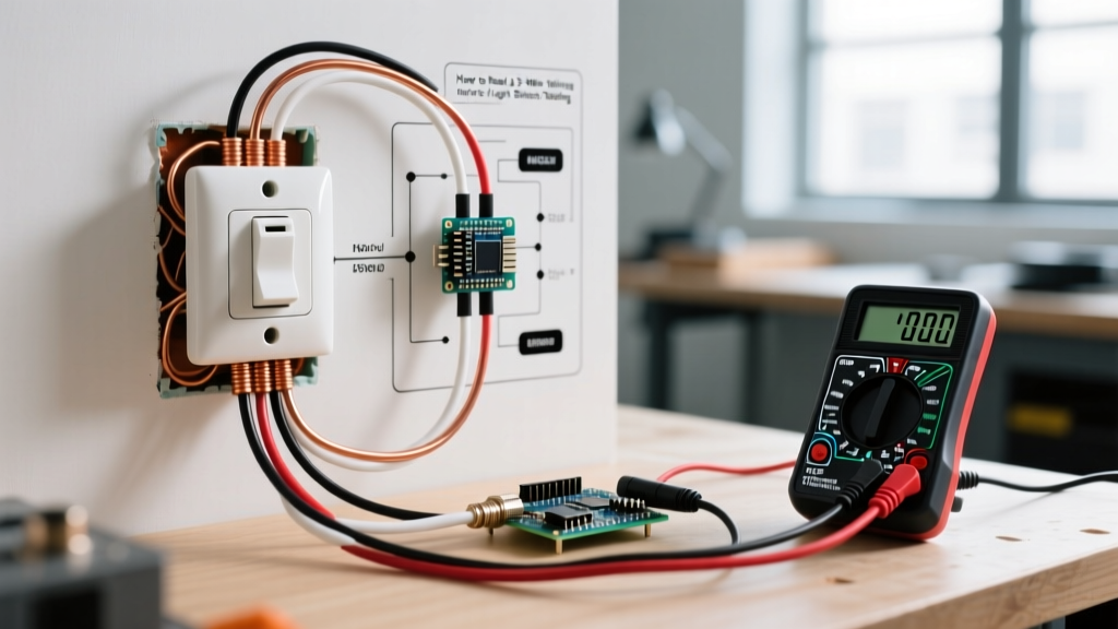
To accurately determine why your outside electrical outlet stopped working, you need a reliable digital multimeter (DMM) capable of measuring AC voltage and continuity. A model like the Klein Tools MM400 or MM600 is ideal for residential diagnostics.
Step 1: Verify True Zero vs. Ghost Voltage
Long outdoor cable runs (such as 12/2 UF-B buried wire) often run parallel to other live circuits. This creates capacitive coupling, inducing a 'ghost voltage' on a disconnected wire. If your DMM reads 50V between hot and ground, do not assume the circuit is partially live.
- Switch your multimeter to the LoZ (Low Impedance) setting. LoZ introduces an internal shunt resistor that bleeds off phantom voltage.
- If the reading drops to 0.0V on LoZ, you have an open hot wire (a broken connection upstream), not a partial short.
- If the reading remains at 120V on LoZ, you have true voltage, and the failure is likely a bad neutral return path.
Step 2: Test the Neutral-to-Ground Bond
A common reason an exterior outlet fails to power high-draw tools (like electric chainsaws or pressure washers) is a floating neutral. With the power ON, measure the voltage between the Neutral (silver) slot and the Ground (U-shaped) hole.
- Normal Reading: 0.0V to 1.5V. (A slight variance is normal due to voltage drop over long wire runs).
- Fault Reading: 120V. This indicates the neutral wire has completely disconnected from the circuit path, likely at a wire nut inside the exterior junction box or at the upstream GFCI's LOAD neutral terminal.
Common Wiring Diagram Errors: Line vs. Load Reversal
When homeowners or amateur handymen replace an outdoor GFCI, they frequently miswire the LINE and LOAD terminals. This is the single most common reason a newly replaced outside electrical outlet stopped working or fails to provide shock protection.
Expert Warning: The LINE terminals (usually marked with black tape or 'LINE' stamping) must receive the incoming power from the breaker panel. The LOAD terminals are strictly for feeding downstream devices. Reversing these will cause the GFCI to function normally under no-load conditions, but it will fail to trip during a ground fault, leaving you exposed to lethal shock hazards in wet environments.
How to verify Line/Load orientation:
- Turn off the breaker and disconnect all wires from the exterior receptacle.
- Cap the bare copper ground wires safely.
- Turn the breaker back ON.
- Use a non-contact voltage tester (NCVT) or multimeter to identify which black wire is hot. This is your LINE hot.
- Identify the corresponding white wire in the same cable jacket; this is your LINE neutral.
- Turn the breaker OFF before connecting the LINE wires to the GFCI.
Upgrading to Code: Weather-Resistant (WR) and Extra-Duty Covers
If your exterior outlet has failed due to environmental damage, simply replacing it with a standard indoor receptacle violates the National Electrical Code (NEC) Article 406.9(A). You must install a Weather-Resistant (WR) rated receptacle. WR devices feature UV-stabilized polycarbonate faces, nickel-plated brass terminal screws to resist corrosion, and stainless steel mounting straps.
Recommended Hardware for 2026 Installations
- Receptacle: Leviton 5280-WMP (20-Amp WR GFCI) or Eaton GFTR2-15W. Expect to pay between $18 and $28 per unit.
- Enclosure: Taymac MM410 Extra-Duty In-Use Cover. The NEC mandates that covers must be 'extra-duty' (weatherproof while a cord is plugged in). The Taymac MM410 accommodates large transformer plugs and costs roughly $22.
- Termination: Use a calibrated torque screwdriver. Leviton specifies 14 in-lbs of torque for #12 AWG copper wire. Overtightening strips the brass threads; undertightening causes arcing and thermal failure.
Sealing the Junction Box
Moisture ingress is the enemy of exterior wiring diagrams. When mounting the new WR receptacle, apply a continuous bead of 100% silicone sealant (such as GE Silicone II) behind the mounting flange of the in-use cover. Do not caulk the bottom weep holes; these are designed to let condensation drain out of the box. If you seal the bottom, trapped humidity will condense on the cold metal box during winter months, eventually corroding the GFCI's internal sense transformer.
Final Safety and Inspection Notes
Before closing up the exterior box and restoring power, ensure all bare copper ground wires are pigtailed together and securely bonded to the green ground screw on the receptacle and the metal junction box (if applicable) using a green 10-32 grounding screw. The U.S. Fire Administration emphasizes that improper grounding in damp locations is a primary catalyst for residential electrical fires. By methodically tracing your wiring diagram from the breaker panel to the exterior LOAD terminals, you can confidently identify why your outside electrical outlet stopped working and implement a permanent, code-compliant repair.