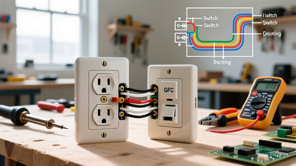

Mastering Receptacle Topologies: A Diagram-First Approach
When installing new electrical outlet configurations, relying on memory or guesswork is a recipe for tripped breakers, damaged appliances, or severe shock hazards. Modern electrical systems require precise terminal mapping, especially with the stringent grounding and fault-protection mandates enforced in the 2023 and upcoming 2026 NEC (National Electrical Code) cycles. This reference guide bypasses generic advice, providing exact wiring diagrams, terminal mappings, and torque specifications for the three most common residential and commercial receptacle configurations.
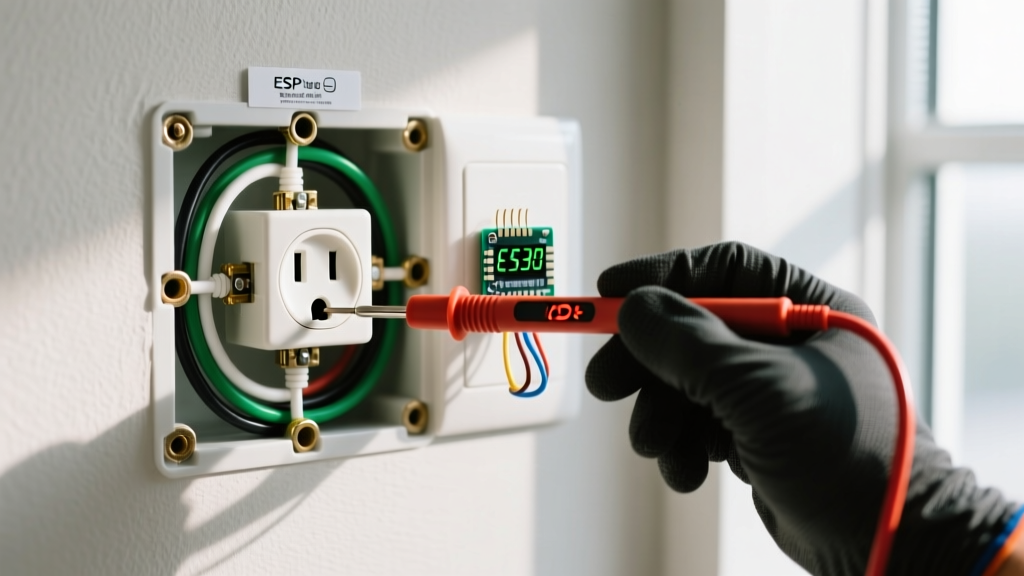
Safety Directive: Always verify the circuit is de-energized using a CAT III or CAT IV non-contact voltage tester (such as the Fluke 2AC-II) and a multimeter before exposing any terminal screws. According to the Occupational Safety and Health Administration (OSHA), failure to verify zero-energy states is a leading cause of residential and commercial electrical fatalities.
Receptacle Terminal Anatomy & Hardware Specifications
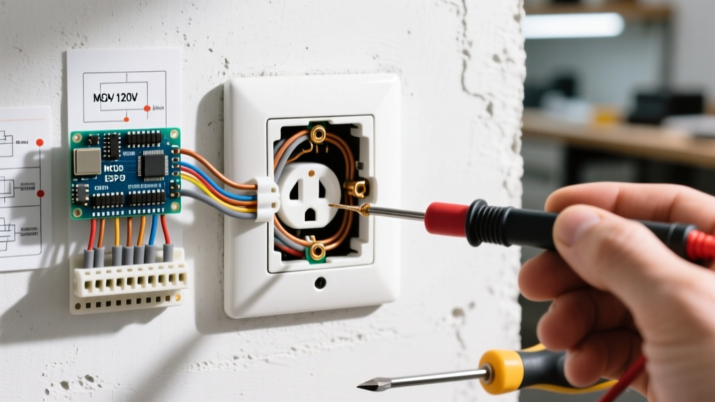
Before executing any wiring diagram, you must understand the physical anatomy of a standard NEMA 5-15R or 5-20R duplex receptacle. Modern tamper-resistant (TR) models feature internal shutters that require equal pressure on both blade slots, but the rear terminal architecture remains standardized.
| Terminal Screw Color | Wire Color (Standard NM-B) | Electrical Function | 2026 Torque Spec (12 AWG) |
|---|---|---|---|
| Brass / Gold | Black (or Red) | Ungrounded Conductor (Hot / Line) | 12 - 14 in-lbs |
| Silver | White | Grounded Conductor (Neutral) | 12 - 14 in-lbs |
| Green | Bare Copper / Green | Equipment Grounding Conductor | 10 - 12 in-lbs |
Expert Note: NEC 110.14(D) strictly requires that terminal connections be torqued to the manufacturer's specifications. As of 2026, electrical inspectors frequently use digital torque screwdrivers (like the Milwaukee 48-22-2804) to verify compliance. Under-torqued wires cause thermal expansion arcing, while over-torqued wires shear the screw heads or damage the brass contact plates.
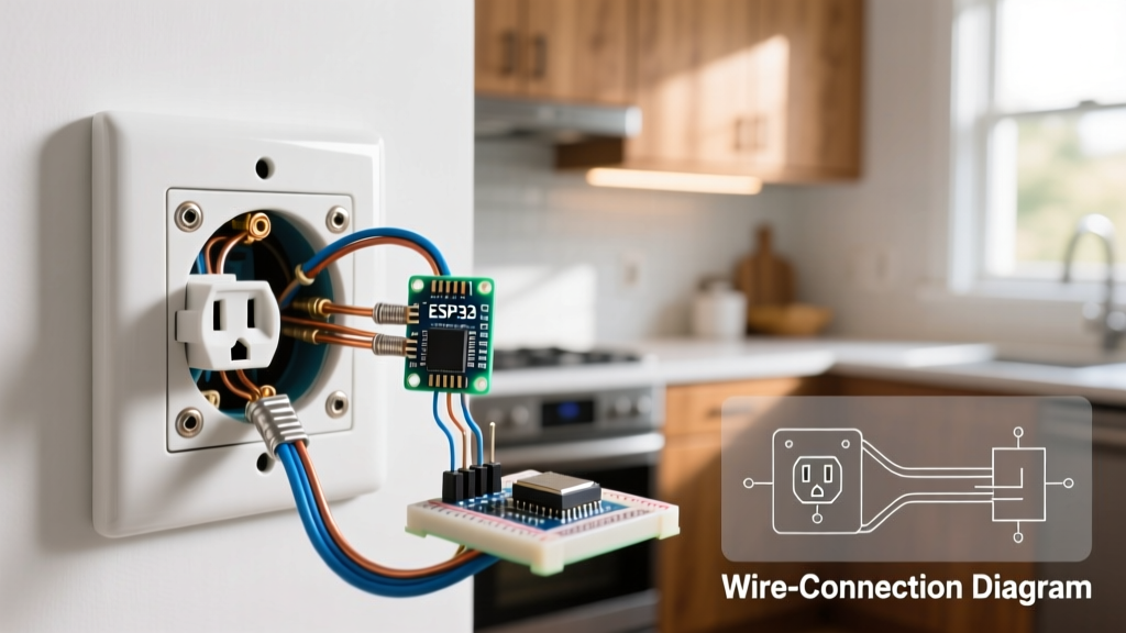
Diagram 1: Standard Duplex Outlet (Pigtail Method)
While 'daisy-chaining' (feeding power in and out directly through the receptacle's side terminals) is common in older homes, the industry standard for installing new electrical outlet replacements is the pigtail method. NEC 300.13(B) dictates that the continuity of the grounded (neutral) conductor must not depend on the receptacle itself. If a daisy-chained neutral burns off or is disconnected, all downstream devices lose their neutral return path, potentially sending 240V across 120V appliances in a multi-wire branch circuit (MWBC).
Step-by-Step Wiring Execution
- Prepare the Pigtails: Cut three 6-inch lengths of 12 AWG THHN wire (Black, White, Green) for a 20A circuit, or 14 AWG for a 15A circuit.
- Splice the Neutrals: Connect the incoming white wire, the outgoing white wire, and the white pigtail using a purple WingNut or a WAGO 221 lever connector. Do not use the receptacle's silver screws to bridge the neutral connection.
- Splice the Grounds: Connect all bare copper wires and the green pigtail with a green wire nut. Attach a separate bonding jumper to the metal electrical box if applicable (NEC 250.148).
- Splice the Hots: Connect incoming and outgoing black wires with the black pigtail.
- Terminate: Form a 'J-hook' with the pigtail ends. Loop the black pigtail clockwise around the brass screw, the white pigtail clockwise around the silver screw, and the green pigtail around the green screw. Tighten to 14 in-lbs.
Diagram 2: GFCI Receptacle (Line vs. Load Mapping)
Ground Fault Circuit Interrupter (GFCI) receptacles, such as the highly rated Leviton GFNT1-W (15A) or GFNT2-W (20A), are mandatory in wet locations per the National Fire Protection Association (NFPA) NEC Article 210.8. The most critical failure point when installing new electrical outlet GFCI setups is confusing the LINE and LOAD terminals.
- LINE Terminals: These connect ONLY to the incoming power source from the breaker panel. They power the GFCI's internal sensing circuitry.
- LOAD Terminals: These connect to downstream standard receptacles, extending GFCI protection to other outlets on the same circuit.
The GFCI Wiring Matrix
| Wire Source | GFCI Terminal | Screw Color | Function |
|---|---|---|---|
| Incoming Hot (Panel) | LINE | Brass | Powers GFCI & Downstream Hots |
| Incoming Neutral (Panel) | LINE | Silver | Powers GFCI & Downstream Neutrals |
| Outgoing Hot (Downstream) | LOAD | Brass | Protects Downstream Hots |
| Outgoing Neutral (Downstream) | LOAD | Silver | Protects Downstream Neutrals |
Troubleshooting Edge Case: If you wire the incoming power to the LOAD terminals, the GFCI will not reset, or it will provide power but fail to trip during a ground fault. Always use the yellow 'FOR LINE CONNECTIONS ONLY' tape included with Leviton and Hubbell models to mark your incoming feed before terminating.
Diagram 3: Split-Wire (Switched) Receptacle
Split-wire receptacles are frequently used in living rooms and kitchens where the top half of the outlet is controlled by a wall switch (for lamps), while the bottom half remains constantly hot (for vacuums or phone chargers). This requires a 3-wire cable (Black, Red, White, Bare) running from the switch/outlet junction.
Breaking the Hot Tab
The defining physical step in this diagram is breaking the brass connecting fin on the hot side of the receptacle. Use a pair of Lineman's pliers (like the Klein Tools 200048EINS) to snap off the small brass tab connecting the top and bottom brass screws. Do not break the silver fin on the neutral side; doing so will isolate the neutrals and cause an immediate open-neutral fault.
Terminal Mapping for Split Receptacles
- Top Brass Screw: Connect the Red wire (Switched Hot returning from the wall switch).
- Bottom Brass Screw: Connect the Black wire (Constant Hot from the breaker).
- Silver Screws: Pigtail the White wire to both silver screws, or use the intact silver fin to bridge them with a single white pigtail.
- Green Screw: Connect the Bare Copper ground.
Common Wiring Failures & Diagnostic Data
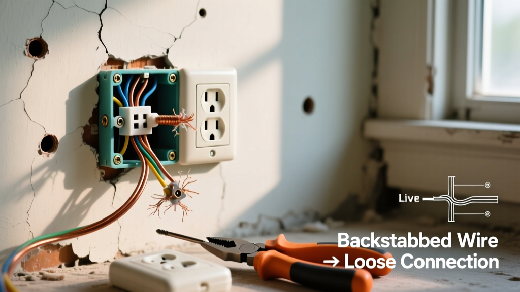
Even with perfect diagram adherence, environmental factors and legacy wiring can introduce faults. The U.S. Consumer Product Safety Commission (CPSC) notes that improper receptacle wiring contributes to over 40,000 residential fires annually. Here is how to identify the most common installation errors using a standard 3-light receptacle tester (e.g., Gardner Bender GFI-3501).
Fault Diagnostic Matrix
| Tester Light Pattern | Fault Condition | Root Cause & Correction |
|---|---|---|
| Yellow-Red-Off | Open Ground | Missing ground wire or disconnected green pigtail. Verify bonding to metal box. |
| Off-Red-Yellow | Reverse Polarity | Hot and Neutral swapped. Black wire is on silver screw; White is on brass. Swap immediately. |
| Yellow-Off-Yellow | Open Neutral | White wire disconnected or daisy-chain neutral broken. Check WAGO connectors or silver terminals. |
| GFCI Won't Trip | Bootleg Ground | Neutral and Ground jumpered together at the receptacle. Highly dangerous; separate them. |
Material Costs and 2026 Procurement
When budgeting for installing new electrical outlet upgrades across a home, material costs have stabilized post-pandemic but vary by grade. As of 2026, a standard residential 15A TR duplex receptacle (like the Leviton T5320-W) costs between $2.50 and $3.50. Commercial-spec grade models (Hubbell 5262-SW), which feature thicker brass contact plates and higher torque tolerance, retail for $6.50 to $8.50. For GFCI installations, expect to pay $16.00 to $22.00 per unit. Always purchase UL-listed or ETL-listed components; uncertified imported receptacles often fail internal thermal cutoff tests and pose severe fire risks.
Final Inspection Checklist
Before pushing the receptacle back into the junction box and installing the faceplate, run through this physical checklist:
- No bare copper wire is exposed outside the terminal saddle.
- The 'J-hook' loops are tight and pulled clockwise.
- Ground wires are neatly folded into the back of the box, not pinched against the metal mounting strap.
- The receptacle mounting strap sits flush against the drywall or plaster ring, utilizing plaster ears if the box is recessed more than 1/4 inch (NEC 314.20).
By strictly adhering to these wiring diagrams and terminal specifications, you ensure a safe, code-compliant, and long-lasting electrical installation that will pass any municipal inspection and protect your home's occupants for decades.