
The Evolution of Outlet Electrical Wiring in Modern Homes
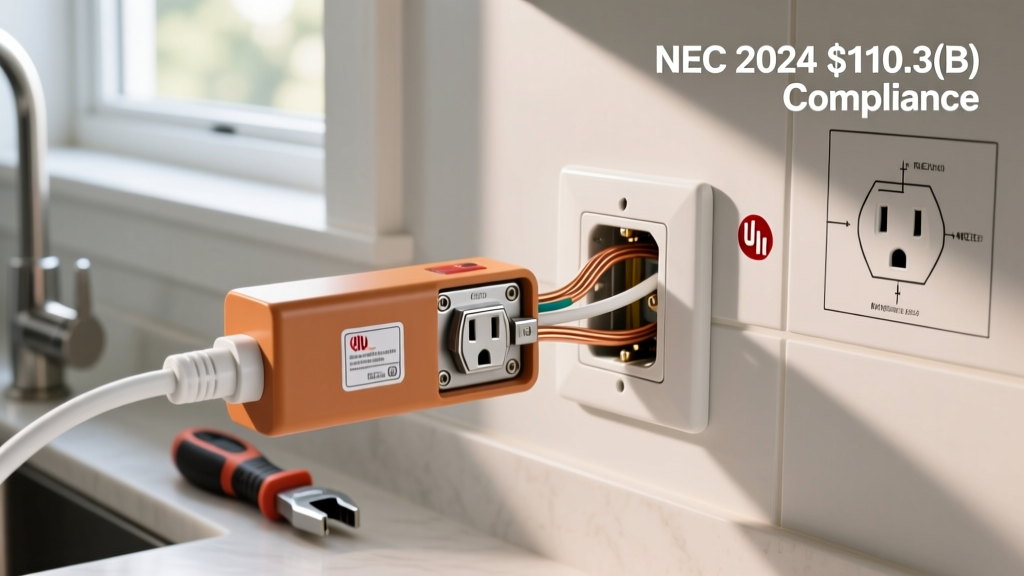
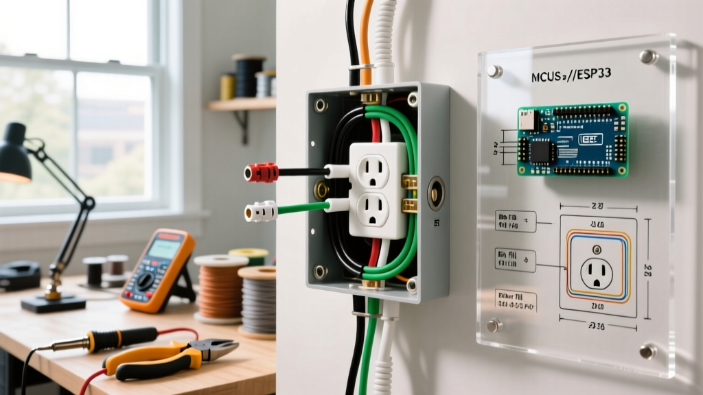
When tackling outlet electrical wiring, the margin for error is measured in millimeters and millinewton-meters. As of 2026, the integration of smart home ecosystems and stricter National Electrical Code (NEC) mandates have transformed how electricians and advanced DIYers approach receptacle installation. Gone are the days of simply shoving stripped wires into push-in backstab terminals. Today, reliable outlet electrical wiring demands an understanding of circuit continuity, torque specifications, and advanced protection schemes.
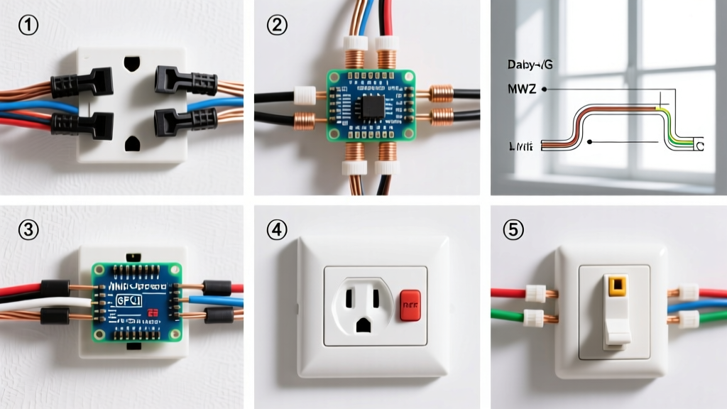
According to the U.S. Consumer Product Safety Commission (CPSC), faulty receptacle wiring remains a leading cause of residential electrical fires. To ensure safety and code compliance, you must select the right wiring topology for your specific scenario. Below, we break down the five most common outlet electrical wiring scenarios, complete with exact product recommendations, NEC references, and professional execution techniques.
Scenario 1: Daisy-Chaining (Downstream Wiring)
Daisy-chaining involves running power to a first receptacle and then using its secondary set of terminals to feed power to the next outlet in the circuit. This is the most common topology for standard 15-amp bedroom and living room circuits.
Execution and Best Practices
- Terminal Selection: Never use the push-in "backstab" holes on standard receptacles like the Leviton 16252-W. The internal spring-loaded brass grips loosen over time due to thermal expansion and contraction, leading to high-resistance arcing. Instead, use the side-wire terminal screws or the screw-and-clamp plates found on commercial-spec receptacles.
- Torque Specifications: Modern NEC 110.14(D) requires terminal connections to be torqued to the manufacturer's specifications. For most standard 15A/20A duplex receptacles, this is between 12 and 14 inch-pounds. Use a calibrated torque screwdriver, such as the Klein Tools 70550, to prevent stripped screws or loose connections.
- Wire Stripping: Strip exactly 3/4-inch of insulation from 14 AWG or 12 AWG solid copper wire. If bare wire is visible past the terminal plate, the risk of a short circuit increases exponentially.
Scenario 2: Pigtailing (The Professional Standard)
While daisy-chaining uses the receptacle itself as a splice point, pigtailing involves joining all incoming and outgoing circuit wires together with a short "pigtail" wire that connects directly to the receptacle. This is the undisputed gold standard for outlet electrical wiring.
Why Pigtailing is Superior
If a daisy-chained receptacle fails or is removed, all downstream outlets lose power—and more dangerously, the neutral path can be severed while the hot path remains live, creating a severe shock hazard. Pigtailing ensures that the circuit's continuity bypasses the receptacle entirely.
Pro Tip: Upgrade from traditional twist-on wire nuts to lever connectors for pigtailing. The Wago 221-413 lever nuts allow for visual confirmation of wire seating and require exactly 11mm of stripped wire. They cost roughly $0.65 each compared to $0.10 for standard Ideal wire nuts, but they reduce installation time by 40% and eliminate the risk of loose twist-on connections.
Scenario 3: Multi-Wire Branch Circuits (Split Receptacles)
In kitchen and dining areas, NEC 210.52 requires countertop receptacles to be served by at least two 20-amp small-appliance branch circuits. To maximize efficiency, electricians often use a Multi-Wire Branch Circuit (MWBC) to wire split receptacles. This involves feeding the top and bottom halves of a single duplex outlet with two separate hot wires sharing a single neutral.
Step-by-Step MWBC Wiring
- Break the Hot Tab: Using needle-nose pliers, snap off the brass connecting fin on the hot (black screw) side of the receptacle. Leave the silver fin on the neutral side completely intact.
- Handle Ties: NEC 210.4 strictly mandates that the two hot breakers feeding an MWBC must be simultaneously disconnected. You must install a listed handle tie (e.g., Eaton CHMT2020) across the two adjacent 20A breakers in your panel, or use a single 2-pole breaker.
- Neutral Sizing: The shared neutral carries only the unbalanced load, but it must still be sized to match the hot conductors (12 AWG for a 20A circuit).
Scenario 4: GFCI Protection (Line vs. Load Wiring)
Ground Fault Circuit Interrupter (GFCI) receptacles are mandatory in wet locations (kitchens, bathrooms, garages, outdoors) per NEC 210.8. A common point of confusion in outlet electrical wiring is the distinction between the "LINE" and "LOAD" terminals on the back of a GFCI device like the Eaton GFTA2-W.
Wiring Downstream Protection
The LINE terminals receive power directly from the breaker panel. The LOAD terminals feed power to downstream standard receptacles, extending GFCI protection to them without needing multiple expensive GFCI devices.
- Identification: Always use a non-contact voltage tester and a multimeter to identify the incoming hot and neutral wires before connecting them to the LINE terminals. Connecting incoming power to the LOAD terminals will result in a receptacle that has power but will not trip or reset, defeating the safety mechanism.
- Testing: After wiring, use a dedicated GFCI tester like the Gardner Bender GFI-3501 to verify that the internal circuitry trips correctly under a simulated 5mA ground fault.
Scenario 5: Isolated Ground (IG) Receptacles
Standard receptacles ground the device yoke (the metal strap) to the grounding terminal screw. In environments with sensitive audio equipment, medical devices, or high-end server racks, electromagnetic interference (EMI) on the standard equipment grounding conductor can cause noise or data errors. Isolated Ground (IG) receptacles, identifiable by an orange triangle on the face (e.g., Hubbell 5262-OIG), solve this.
The IG Wiring Technique
When wiring an IG receptacle, an insulated green grounding wire is run alongside the hot and neutral conductors all the way back to the main service panel's ground bus, completely bypassing the metal junction boxes and conduit. The metal yoke of the IG receptacle is still bonded to the local box ground for physical safety, but the dedicated green wire provides a "clean" noise-free path for sensitive electronics. Note that IG receptacles are rarely needed in standard residential settings and are primarily a commercial/industrial solution.
Comparison Matrix: Outlet Wiring Topologies
| Wiring Scenario | Material Cost (Per Outlet) | Reliability & Safety | Best Application |
|---|---|---|---|
| Daisy-Chain (Side-Wire) | $2.50 (Receptacle only) | Moderate (Downstream vulnerability) | Simple living room runs, low-draw lighting circuits |
| Pigtailing (Wago 221) | $4.25 (Receptacle + Connectors) | Excellent (Continuous circuit path) | All general-purpose circuits, smart receptacles |
| MWBC (Split Receptacle) | $3.00 + Panel Handle Tie | High (Requires strict NEC adherence) | Kitchen countertops, dining room buffets |
| GFCI Line/Load | $18.00 (GFCI Device) | Critical (Life-safety protection) | Bathrooms, garages, exterior walls |
| Isolated Ground (IG) | $12.00 (IG Receptacle) | Specialized (EMI mitigation) | Home studios, medical equipment, server racks |
Final Thoughts on Code Compliance and Safety
Mastering outlet electrical wiring requires moving beyond basic connectivity and embracing the engineering principles behind the NEC. As the National Fire Protection Association (NFPA) continues to update the NEC to address modern electrical loads and smart home technologies, staying informed is your best defense against fire hazards and equipment failure.
Whether you are pigtailing a 20-amp kitchen circuit with Wago lever nuts or configuring the load terminals on a GFCI receptacle, always verify your work with a calibrated multimeter. Turn off the main breaker, lock out the panel, and never assume a wire is dead until you have tested it yourself. Proper outlet electrical wiring is not just about making the device work; it is about ensuring the system operates flawlessly and safely for decades to come.