
The Anatomy of a Dead Outlet: Reading the Wiring Diagram
When one electrical outlet stopped working while the rest of the room remains powered, the issue rarely stems from the main breaker panel. Instead, the fault lies within the localized branch circuit topology. To diagnose this accurately, electricians rely on wiring diagram references to trace the flow of current from the line (source) to the load (downstream devices). In standard residential 15-amp and 20-amp branch circuits, receptacles are wired in parallel but are physically daisy-chained through the device yoke or via wire nuts in the backbox.
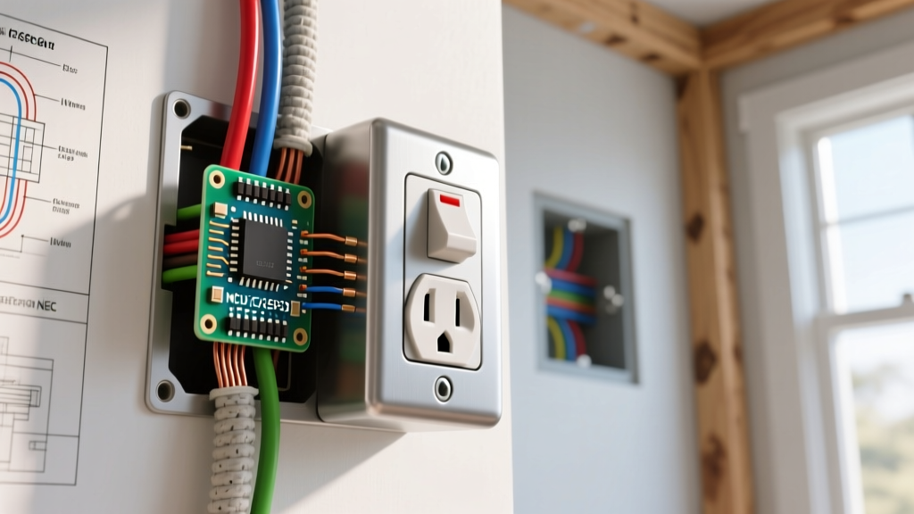
Understanding the schematic of your specific wiring layout is the first step in isolating the fault. A standard wiring diagram for a pass-through receptacle shows the hot (black) and neutral (white) conductors entering the 'LINE' side of the device, and a second set of conductors exiting the 'LOAD' side to feed downstream outlets. If the outlet in question is at the end of the run, the diagram simplifies to a single line and neutral terminating at the device. By mapping your physical outlets to this mental schematic, you can determine whether the failure is an isolated terminal fault or a severed upstream node.
Backstab vs. Screw Terminal Failures
The most common schematic failure point for a single dead receptacle is the push-in backwire connector (often called 'backstabbing'). While modern 20-amp commercial-grade receptacles (like the Leviton 5362-W) feature robust internal screw-clamp backwiring, older or builder-grade 15-amp models rely on spring-loaded brass clips for 14 AWG wire. Over years of thermal expansion and contraction, these springs lose tension, creating high-resistance connections. On a wiring diagram, this manifests as an open circuit at the exact node of the receptacle. The fix requires abandoning the backstab ports entirely, stripping 5/8-inch of insulation from the conductor, and terminating it under the side binding screws.
Step-by-Step Diagnostic Protocol (2026 Standards)
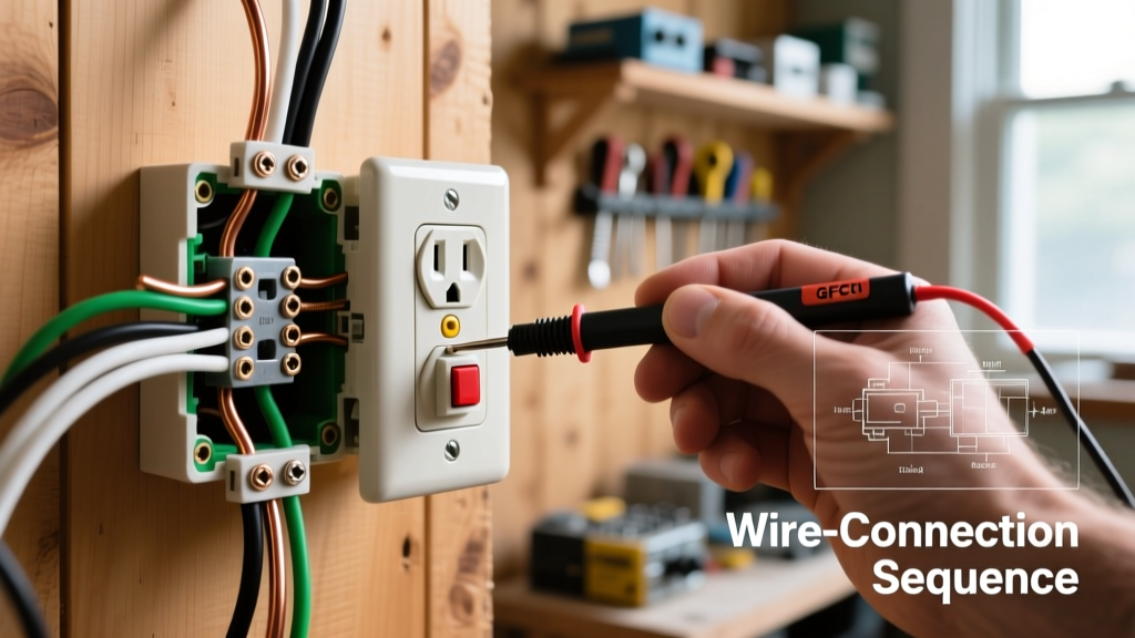
To move beyond guesswork, you must verify the circuit state using a True RMS digital multimeter, such as the Fluke 117 (retailing around $190). A standard neon voltage tester is insufficient for identifying floating neutrals or induced phantom voltages. Follow this diagnostic sequence to map your physical readings against the expected wiring diagram values:
- Verify Breaker State: Confirm the 15A or 20A breaker is fully seated in the ON position. Reset any tripped GFCI or AFCI breakers in the panel.
- Test Hot-to-Ground (H-G): Insert the black probe into the shorter (hot) slot and the red probe into the ground hole. Expected reading: 120V (acceptable range: 114V–126V per ANSI C84.1 standards). If 0V, the hot leg is severed upstream.
- Test Hot-to-Neutral (H-N): Move the red probe to the longer (neutral) slot. Expected reading: 120V. If H-G reads 120V but H-N reads 0V, you have an open neutral fault at the device or the immediate upstream node.
- Test Neutral-to-Ground (N-G): Place probes in the neutral and ground slots. Expected reading: 0V to 2V. A reading of 120V indicates a reversed polarity or a severely compromised neutral bus connection.
Troubleshooting Matrix: Symptom to Wiring Fault
Use the following reference matrix to cross-reference your multimeter readings with the corresponding wiring diagram fault and the required physical repair.
| Multimeter Symptom | Wiring Diagram Fault | Physical Root Cause | Required Repair Action |
|---|---|---|---|
| H-G: 0V | H-N: 0V | Open Line (Hot) Node | Tripped upstream GFCI, broken pigtail, or failed backstab on upstream device. | Trace upstream to first working outlet; repair LOAD-side connections. |
| H-G: 120V | H-N: 0V | Open Neutral Node | Disconnected white wire, loose wire nut, or severed neutral at the yoke. | Re-terminate neutral using Wago 221-413 lever nuts or side-screw binding. |
| H-G: 120V | H-N: 120V | N-G: 120V | Reversed Polarity / Open Ground | Hot and neutral swapped, or ground wire completely detached from the box. | Swap black and white wires on brass/silver screws; bond ground to green screw. |
| H-G: 40V-80V (Fluctuating) | High-Resistance Connection | Thermal creep on backstabbed wire, loose binding screw, or corroded terminal. | Cut back damaged wire, strip fresh 5/8-inch, and torque screw to 14 in-lbs. |
Decoding GFCI and AFCI Load-Side Cascading Failures
A frequent reason why one electrical outlet stopped working—especially in homes built or renovated after 2014—is a hidden Ground Fault Circuit Interrupter (GFCI) or Arc Fault Circuit Interrupter (AFCI) protecting the circuit's load side. According to the National Electrical Code (NFPA 70), GFCI protection is mandated for kitchens, bathrooms, garages, exteriors, and unfinished basements. However, many builders wire standard interior outlets (like a hallway or bedroom receptacle) to the LOAD terminals of a garage or bathroom GFCI to save on breaker costs.
When the upstream GFCI detects a ground fault (as little as 5mA of leakage), it trips and cuts power to all downstream LOAD-side nodes. On your wiring diagram, the dead outlet is not an isolated failure but a casualty of a tripped upstream protection device. Always use a Klein Tools RT250 GFCI Receptacle Tester ($35) to map out which outlets are tied to which GFCI nodes. If you discover this cascading topology, consider rewiring the downstream outlets to the LINE side of the GFCI (if they do not require ground-fault protection by code) or installing a dedicated 20A GFCI breaker in the panel to eliminate point-of-use daisy-chain vulnerabilities.
Professional Repair Techniques and 2026 Cost Breakdown
Once the wiring diagram fault is isolated, the physical repair must meet modern safety standards. The days of twisting wires together with cheap vinyl electrical tape are over. Professional electricians now rely on push-in lever connectors and calibrated torque tools to ensure permanent, low-resistance terminations.
Essential Tools and Materials
- Wago 221-413 Lever Nuts: Ideal for pigtailing 14 AWG and 12 AWG solid or stranded copper. Cost: ~$0.45 per connector. They provide a transparent housing to visually verify wire seating and eliminate the risk of loose wire nut vibrations.
- Leviton T5320-W 15A Tamper-Resistant Receptacle: Features heavy-duty brass side-wiring clamps and back-wire pressure plates. Cost: ~$3.50 per unit. The internal tamper-resistant shutters comply with NEC Article 406.12.
- Wiha 320P Torque Screwdriver: Standard brass binding screws on 15A/20A receptacles require exactly 14 in-lbs of torque to prevent thermal loosening without stripping the brass threads. Cost: ~$110 for a calibrated set.
The Pigtailing Method
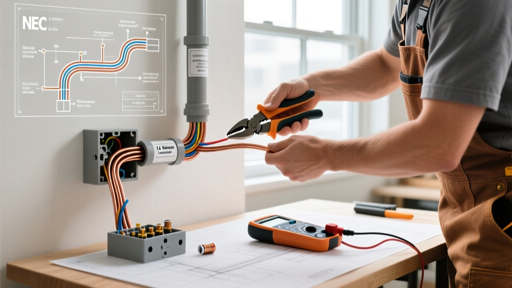
If the dead outlet was previously wired as a pass-through (daisy-chain) using the device's internal brass yoke, best practice dictates converting it to a 'pigtail' configuration. This ensures that if the receptacle itself fails in the future, the downstream outlets remain powered. Cut a 6-inch piece of 14 AWG (or 12 AWG for 20A circuits) solid copper wire. Strip 5/8-inch of insulation from both ends. Use a Wago 221-413 to connect the incoming LINE hot, the outgoing LOAD hot, and the new pigtail hot. Repeat for the neutral. Finally, terminate the pigtails to the new receptacle's side screws, applying 14 in-lbs of torque. Wrap the sides of the receptacle with 3M TemFlex 1700 electrical tape to cover the exposed terminal screws before pushing it back into the junction box, ensuring no bare ground wires can short against the hot terminals.
Safety Warning: Always de-energize the circuit at the main service panel before opening any junction box. The Occupational Safety and Health Administration (OSHA) mandates strict lockout/tagout procedures for electrical work. Verify zero voltage with a CAT-III rated multimeter before touching any conductors. For comprehensive home safety guidelines, refer to the Electrical Safety Foundation International (ESFI).
By treating a dead outlet not as a random anomaly but as a predictable node failure on a branch circuit wiring diagram, you can systematically isolate the fault, upgrade the termination methodology, and restore safe, reliable power to your home's electrical network.