
Decoding the Wiring Diagram for 50 Amp RV Outlet Configurations
Installing a 50-amp RV receptacle is one of the most demanding residential electrical projects due to the continuous high-current draw of modern recreational vehicles. When referencing a wiring diagram for 50 amp RV outlet installations, you are working with a NEMA 14-50R configuration. This is a 4-wire, 120/240V split-phase system capable of delivering up to 12,000 watts. Unlike older 3-prong NEMA 10-50 setups (which are now strictly prohibited for new installations by the National Electrical Code), the 14-50R separates the neutral and equipment grounding conductors, providing a critical safety path for fault currents.
Whether you are wiring an outdoor RV pedestal or a garage workshop drop, understanding the precise terminal mapping, wire gauge requirements, and torque specifications is non-negotiable. A loose connection on a 50-amp circuit will generate immense heat, leading to melted faceplates, arcing, and potential structure fires.
Terminal Mapping and Wire Color Codes
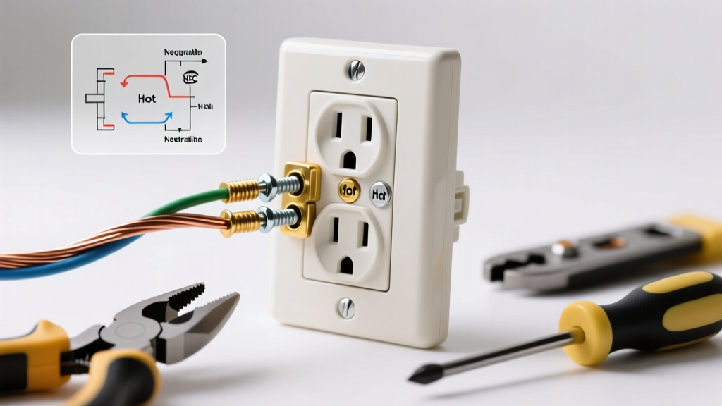
The NEMA 14-50R receptacle features four distinct terminals. When viewing the back of the receptacle with the grounding pin at the bottom, the terminal layout follows a strict standard. Below is the definitive mapping for your wiring diagram:
| Terminal Label | Wire Color (Copper) | Wire Color (Aluminum) | Function | Voltage Potential |
|---|---|---|---|---|
| X (Left Brass) | Black | Black or Red | Hot Leg 1 | 120V to Neutral / 240V to Y |
| Y (Right Brass) | Red | Black or Red (with phase tape) | Hot Leg 2 | 120V to Neutral / 240V to X |
| W (Silver) | White | White or Gray | Neutral | 120V return path |
| G (Green) | Bare or Green | Bare or Green | Equipment Ground | 0V (Fault path only) |
Component Selection: Receptacle and Breaker Specifications
The most common failure point in RV electrical systems is not the wiring itself, but the receptacle. Standard residential-grade receptacles (like the Leviton 279-S00) are rated for 50 amps but often utilize lighter internal bus bars and smaller screw terminals. When an RV runs dual air conditioners, a residential refrigerator, and an electric water heater simultaneously, the continuous draw can hover near 40-45 amps for hours. This causes thermal expansion and contraction in residential receptacles, eventually loosening the terminal screws.
Expert Recommendation: Always specify an industrial or commercial-grade receptacle for RV applications. The Hubbell 9450A is the gold standard for RV pedestals. It features massive internal bus bars, high-impact thermoset housing, and heavy-duty terminal screws designed to withstand high insertion forces and continuous thermal cycling.
For the overcurrent protection device (OCPD), you must use a 50-amp, 2-pole breaker. If your panel is a Square D Homeline, use the HOM250CP; for Siemens, use the Q250. Ensure your wire gauge matches the breaker and the conductor material:
- Copper: 6 AWG THHN/THWN-2 (rated 65A at 75°C, perfectly safe for a 50A breaker).
- Aluminum: 4 AWG XHHW-2 or USE-2 (rated 65A at 75°C). Never use 6 AWG aluminum for a 50A breaker, as its ampacity is only 50A at 60°C and 55A at 75°C, leaving no margin for continuous load derating.
Step-by-Step Termination and Torque Requirements
Following the wiring diagram is only half the battle; the physical execution dictates the lifespan of the installation. The National Fire Protection Association (NFPA) mandates specific torque values for electrical terminations to prevent thermal runaway.
- Strip the Conductors: Use a calibrated wire stripper to remove exactly 5/8 inch of insulation from the 6 AWG or 4 AWG wires. Do not nick the copper or aluminum strands, as this creates a localized hot spot.
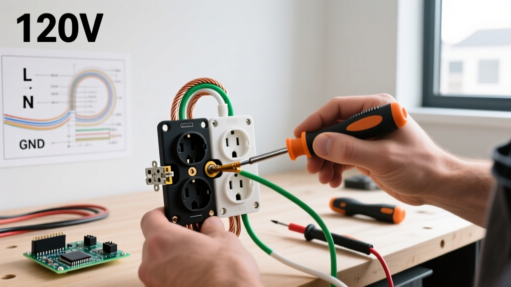
- Seat the Wires: Insert the wires into the appropriate X, Y, W, and G terminals. Ensure no bare wire is visible outside the terminal saddle, and no insulation is trapped under the screw head.
- Apply Anti-Oxidant (Aluminum Only): If using aluminum wire, apply a UL-listed antioxidant paste (like Noalox) to the exposed strands before insertion to prevent galvanic corrosion and oxidation.
- Torque to Specification: You must use a calibrated torque screwdriver. For the Hubbell 9450A, torque the Line (X, Y) and Neutral (W) screws to 75 in-lbs, and the Ground (G) screw to 35 in-lbs. For residential Leviton models, the standard is typically 45 in-lbs across all terminals. Never guess the tightness by hand.
- Secure the Yoke: Mount the receptacle to the weatherproof box using the provided stainless steel screws. Ensure the gasket is seated flat to maintain the NEMA 3R (rainproof) rating of the outdoor enclosure.
The NEC GFCI Mandate and RV EMS Nuisance Tripping
Any modern wiring diagram for 50 amp RV outlet setups must address Ground Fault Circuit Interrupter (GFCI) requirements. Starting with the 2020 NEC (and carried into the 2023 and upcoming 2026 cycles), Section 210.8(F) requires GFCI protection for all 15A, 20A, 30A, and 50A receptacles rated 125V or 250V that supply RVs.
This code change caused massive upheaval in the RV industry. Modern RVs are equipped with Electrical Management Systems (EMS) and large inverter/chargers that utilize Y-capacitors to filter electromagnetic interference. These capacitors naturally bleed a small amount of current (often 4mA to 6mA) to the ground wire. Because a standard 50-amp GFCI breaker trips at a 4mA to 6mA differential, plugging a modern RV into a code-compliant GFCI-protected 14-50R often results in immediate, nuisance tripping.
Navigating the GFCI Dilemma in 2026
The RV Industry Association (RVIA) has been actively working with the NFPA to address this incompatibility. If you are wiring an RV outlet today, you have a few practical paths:
- Install the GFCI Breaker: Comply strictly with NEC 210.8(F) by installing a 50A GFCI breaker (e.g., Eaton BR250GFI). Advise the RV owner that they may need to update their onboard EMS or disable certain inverter ground-bonding features to prevent tripping.
- Hardwire a Sub-Panel: Instead of wiring a receptacle, hardwire a dedicated RV sub-panel directly to the home's main feeder. Hardwired connections do not fall under the 210.8(F) receptacle GFCI mandate, entirely bypassing the nuisance tripping issue while maintaining safety.
- Local AHJ Variances: Consult your local Authority Having Jurisdiction (AHJ). Some municipalities have issued temporary variances or interpretations regarding existing RV pedestals versus new construction.
Troubleshooting Common 50-Amp RV Wiring Failures
Even with a perfect wiring diagram, field conditions can introduce errors. If the RV's EMS displays a fault code or the breakers trip immediately upon connection, check these specific failure modes:
1. Reversed Hot Legs or Open Neutral
If the RV's EMS reads 240V on a single leg and 0V on the other, or throws a 'Reverse Polarity' code, the X and Y hot wires may be swapped, or the neutral (W) is floating. An open neutral on a 120/240V multi-wire branch circuit is catastrophic; it forces 120V appliances to share a series circuit, potentially sending 240V through a 120V microwave or TV, instantly destroying the electronics.
2. Neutral-to-Ground Bond at the Receptacle
The neutral and ground must never be bonded at the RV receptacle. The only place the neutral and ground are bonded is at the main service disconnect (the first point of disconnect from the utility). If a sub-panel or outdoor pedestal is used, the neutral bus bar must be isolated from the metal enclosure. A bonded neutral at the pedestal will cause neutral return current to flow on the bare ground wire, tripping GFCI breakers and creating a shock hazard on the RV chassis.
3. Voltage Drop from Undersized Feeders
If the run from the main panel to the RV pedestal exceeds 50 feet, 6 AWG copper will experience significant voltage drop under a 40+ amp load. RV appliances (especially A/C compressors) can suffer permanent damage if voltage drops below 108V. For runs between 50 and 100 feet, upsize your feeder to 4 AWG copper or 2 AWG aluminum to maintain a voltage drop of less than 3% at full load.
By strictly adhering to the NEMA 14-50R wiring diagram, utilizing commercial-grade components, and respecting modern NEC GFCI requirements, you will deliver a safe, high-performance power supply capable of supporting the most advanced RVs on the market.