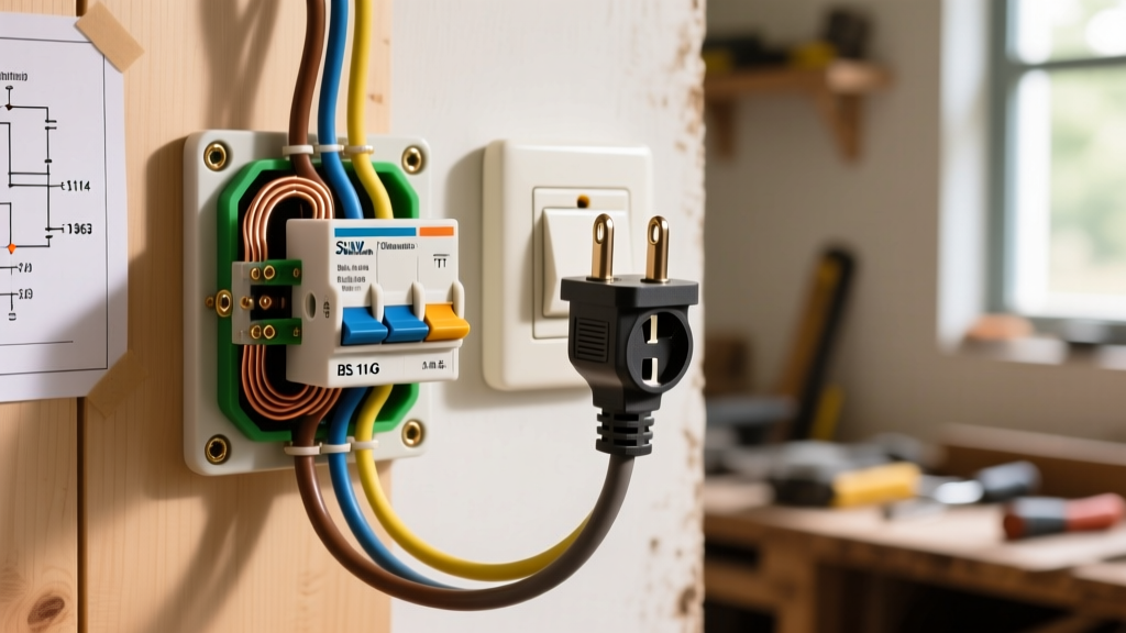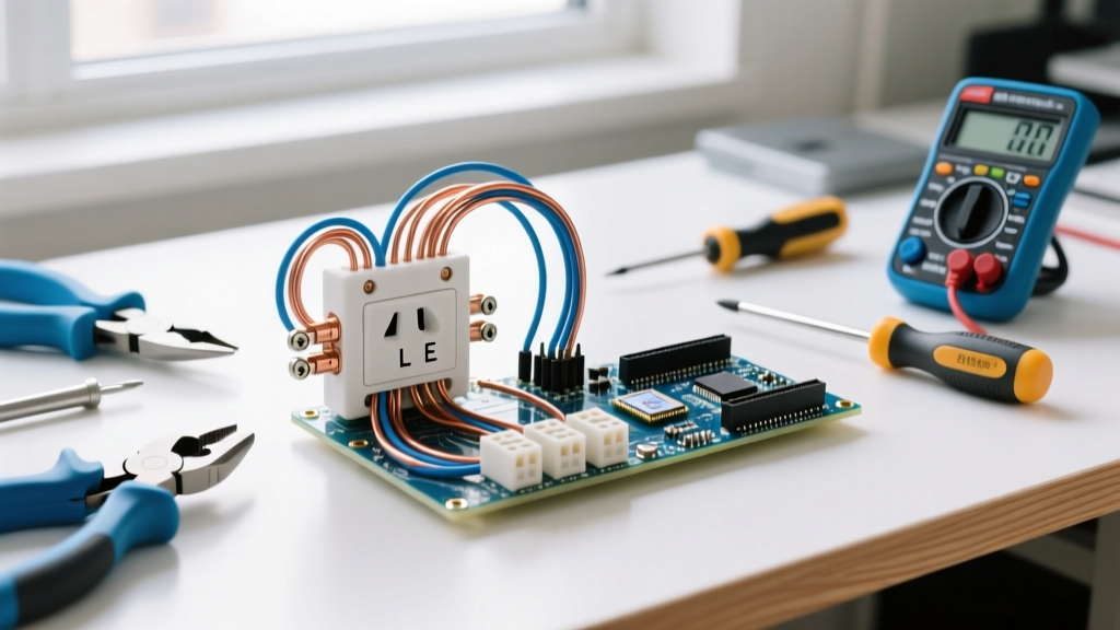

The Critical Role of Inspection in Outlet Installation
Learning how to put in new electrical outlet wiring is only half the battle; the true mark of a professional-grade installation lies in the rigorous inspection and testing phases. According to the Electrical Safety Foundation International (ESFI), electrical distribution and lighting equipment are responsible for tens of thousands of residential fires annually, with loose connections and improper grounding acting as primary culprits. In 2026, with the widespread adoption of the latest National Electrical Code (NEC) standards, simply twisting wires together and pushing them into the wall is a liability. This guide transitions beyond basic wiring, focusing on the advanced inspection metrics, torque specifications, and diagnostic testing required to ensure your new receptacle is safe, code-compliant, and built to last.
Phase 1: Pre-Rough-In Inspection & Box Fill Verification
Before you even strip a wire, you must verify that the electrical box can legally and physically house the new device. NEC Article 314.16 dictates strict box fill calculations to prevent wire crushing and insulation damage, which can lead to short circuits.
Calculating Box Fill for Modern Receptacles
Modern smart outlets and GFCI/AFCI receptacles are significantly deeper than standard duplex receptacles. A standard 15A duplex receptacle might require 1.5 inches of depth, while a Leviton GFNT2-W GFCI or a smart Wi-Fi outlet can require 2.75 inches or more.
- Box Volume: A standard 4x4x2-1/8 inch metal box provides 30.3 cubic inches of space.
- Wire Allowance: For 12 AWG wire, multiply 2.25 cubic inches by the number of current-carrying conductors entering the box.
- Device Allowance: The receptacle itself counts as two wire allowances (e.g., 2 x 2.25 = 4.5 cubic inches for 12 AWG).
- Clamp and Ground Allowance: Add 2.25 cubic inches for internal clamps and 2.25 cubic inches for all equipment grounding conductors combined.
Expert Edge Case: If you are upgrading from a standard outlet to an AFCI/GFCI combination device in an older, shallow 4x4x1.5 inch box (21 cubic inches), you will likely fail the box fill inspection. You must install a box extender ring or replace the box entirely to accommodate the massive heat sink and electronics housing on the back of the device.
Phase 2: How to Put in New Electrical Outlet with Precision Torque
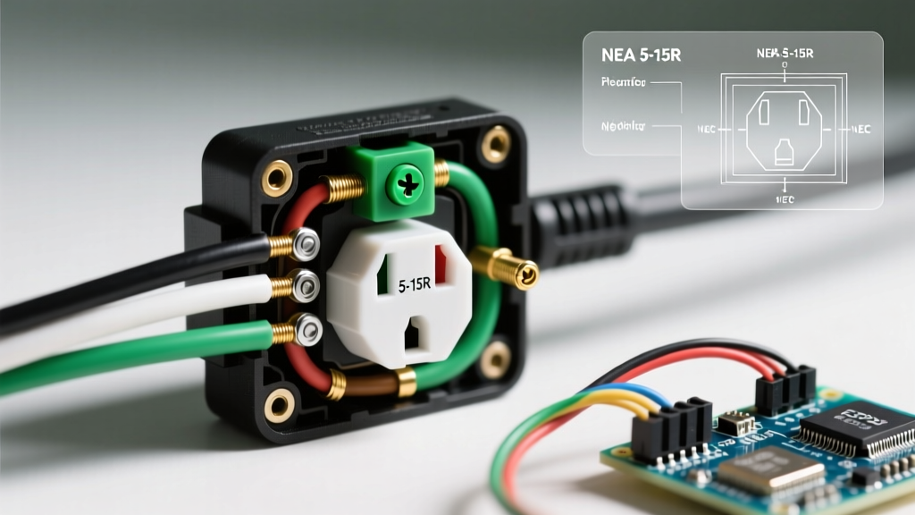
When researching how to put in new electrical outlet hardware, most DIY guides stop at wrapping the wire around the terminal screw. However, the National Fire Protection Association (NFPA) enforces NEC 110.14(D), which mandates that all electrical connections be tightened to the manufacturer's specified torque using a calibrated torque screwdriver.
The Torque Specification Matrix
Under-torqued screws lead to thermal expansion and contraction cycles that loosen the connection over time, creating high-resistance arcing. Over-torqued screws strip the brass threads or sheer the screw head. Here are the exact specifications for standard 2026 receptacles:
| Receptacle Type / Model | Wire Gauge | Required Torque (in-lbs) | Recommended Calibrated Tool |
|---|---|---|---|
| Leviton 15A Standard (R52-05320-000) | 14 AWG | 12 - 14 in-lbs | Wiha 320P (Approx. $45) |
| Leviton 20A Spec Grade (5362-W) | 12 AWG | 14 - 16 in-lbs | Milwaukee 48-22-2812 ($65) |
| Eaton GFCI (GFTR2-W) | 12 AWG | 14 in-lbs (Terminal) | Klein Tools 32500 ($55) |
Pro-Tip: Always use the side-wire clamp plates rather than looping the wire around the screw hook. Back-wiring (inserting the wire straight into the rear terminal where a screw tightens a clamp plate) provides superior surface contact and is highly recommended for 12 AWG solid copper wire.
Phase 3: Post-Installation Testing & Diagnostics
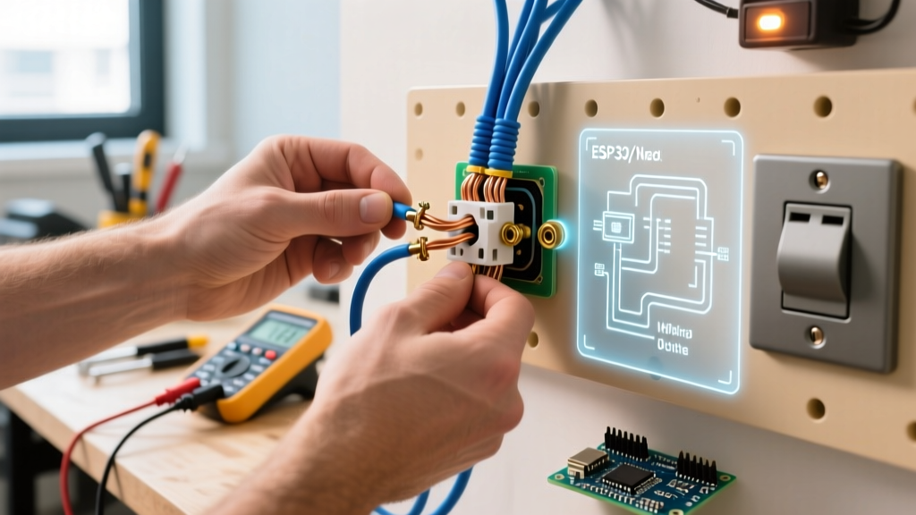
Once the outlet is physically mounted and the faceplate is secured, you must validate the electrical integrity of the circuit. A standard $8 three-light receptacle tester is insufficient for professional validation. You need to test ground impedance, polarity, and trip curves.
Comprehensive Testing Matrix
| Test Parameter | Required Diagnostic Tool | Expected Reading / Result | Failure Mode / Edge Case |
|---|---|---|---|
| Hot/Neutral Polarity | Klein Tools RT105 ($45) | Correct wiring indication | Reversed polarity at the panel or upstream junction. |
| Ground-to-Neutral Voltage | Fluke 117 Multimeter ($200) | < 2.0 Volts AC | Shared neutral or overloaded neutral bus bar. |
| GFCI Trip Time (at 6mA) | Sperry GFI-3500A ($15) | Trips in 20-25 milliseconds | Fails to trip; indicates dead internal solenoid. |
| Ground Impedance Loop | Amprobe AT-3500 ($350) | < 25 Ohms | High impedance; ground rod failure or loose panel bond. |
Advanced Diagnostics: Uncovering the 'Bootleg Ground'
One of the most dangerous edge cases encountered during outlet inspection is the 'bootleg ground.' This occurs when a previous installer connects a jumper wire between the neutral terminal and the ground terminal on the receptacle to trick a standard three-light tester into showing a 'correct' reading.
Safety Warning: A bootleg ground is a severe shock hazard. If a neutral wire disconnects upstream, the metal chassis of any plugged-in appliance will become energized at 120V, relying on the user as the path to ground. Always verify ground integrity with a multimeter, not just a plug-in tester.
How to test for a bootleg ground:
- Set your multimeter to AC Voltage.
- Measure Hot to Neutral (should be ~120V).
- Measure Hot to Ground (should be ~120V).
- Measure Neutral to Ground (should be < 2V).
- Turn off the circuit breaker. Measure resistance (Ohms) between Neutral and Ground at the receptacle. If you read near 0 Ohms, you have a bootleg ground or a neutral-ground bond error that must be corrected immediately.
Common Inspection Failures and Remediation
During final walkthroughs and OSHA electrical safety compliance checks, inspectors frequently flag the following specific installation errors:
- Pigtailing Errors on Multi-Wire Branch Circuits (MWBC): If you are replacing an outlet on an MWBC (where two hot wires share one neutral), you MUST use a pigtail for the neutral wire. Breaking the neutral tab on the receptacle itself to pass the neutral through will de-energize the downstream circuit when the receptacle is removed, violating NEC 300.13(B).
- Insulation Scoring: Using a dull utility knife to strip Romex sheathing often scores the copper conductor underneath. This creates a micro-fracture that will eventually snap under thermal cycling. Always use dedicated cable slitters like the Klein 1412.
- Missing GFCI Protection in Wet Zones: As of the 2023/2026 NEC updates, GFCI protection is required in all 125-volt through 250-volt receptacles supplied by single-phase branch circuits rated 150 volts or less to ground, 50 amperes or less, in areas like kitchens, bathrooms, garages, and even unfinished basements. Standard receptacles in these zones will fail inspection.
Expert FAQ: Outlet Testing & Troubleshooting
Why does my new AFCI/GFCI outlet trip immediately upon resetting?
If a combination AFCI/GFCI receptacle (like the Leviton AGFTR2) trips instantly, you likely have a shared neutral downstream, a ground fault in a connected appliance, or the line/load wires are reversed. AFCI sensors are highly sensitive to neutral-to-ground cross-connections. Use a tone tracer to verify that the neutral wire connected to the LOAD terminal belongs exclusively to the same hot wire.
Is it acceptable to use the push-in backwire holes on a standard 15A outlet?
No. While older 'stab-in' push-wire connections rely on a small brass spring clip that loses tension over time, modern 'back-wire' clamps (where you insert the wire and tighten a screw to clamp it) are perfectly safe. Inspectors will fail an installation if they see standard push-in connections on 12 AWG wire, as most push-in holes are only rated for 14 AWG solid copper.
How do I test if the outlet box is properly grounded in a conduit system?
In commercial or older residential installations using EMT (Electrical Metallic Tubing) without a dedicated ground wire, the metal conduit acts as the Equipment Grounding Conductor (EGC). To test this, measure the voltage between the Hot terminal and the bare metal box. If it reads a solid 120V, the conduit path is intact. If it reads significantly lower or fluctuates, the conduit couplings are loose, and you must pull a dedicated green grounding wire through the pipe.