
Understanding the 12V Accessory Socket Standard (SAE J563)
While universally referred to by DIYers as a 'cigarette lighter plug,' the modern 12V DC accessory receptacle is governed by the SAE J563 standard. Originally designed in the 1950s to heat a bimetallic strip for lighting tobacco, the physical socket has evolved into the global standard for 12V DC power delivery in RVs, marine vessels, and overland builds. As of 2026, while many newer vehicles integrate USB-C PD (Power Delivery) directly into the dash, the 12V barrel socket remains essential for high-draw accessories like portable air compressors, 12V coolers, and inverters.
When designing a wiring diagram for a cigarette lighter plug, you are not just connecting two wires; you are building a high-current DC circuit capable of handling 120W to 180W continuously. DC circuits are unforgiving. Unlike AC household wiring, 12V DC requires heavy-gauge wire to mitigate voltage drop and robust overcurrent protection to prevent thermal events.
CRITICAL SAFETY WARNING: Direct Current (DC) arcs do not self-extinguish at zero-crossing like Alternating Current (AC). A loose connection in a 12V socket can sustain a plasma arc that will melt the ABS plastic housing and ignite surrounding insulation in seconds. Never bypass the inline fuse.
Essential Components & 2026 Cost Breakdown
Before cutting into your RV or boat's panel, gather the correct marine and automotive-grade components. Avoid the $4 Amazon multipacks; their internal springs lack the tension required for high-draw plugs, leading to arcing.
| Component | Recommended Specification | Est. Cost (2026) | Notes |
|---|---|---|---|
| 12V Receptacle | Marinco 12V or Nilight Heavy-Duty (Bakelite/Ceramic core) | $12 - $24 | Must feature a minimum 1-1/8" (28.5mm) mounting depth. |
| Wire (Positive & Negative) | 12 AWG Stranded Marine Tinned Copper (Duplex) | $1.10 / ft | Tinned copper resists galvanic corrosion in marine/RV environments. |
| Overcurrent Protection | Blue Sea Systems ST Blade Fuse Block + 15A ATO Fuse | $28 (block) + $1 (fuse) | Mount as close to the battery positive terminal as possible. |
| Terminations | 3M Adhesive-Lined Heat Shrink Ring/Fork Terminals | $0.45 / ea | Adhesive lining creates a waterproof seal against capillary action. |
| Inline Switch (Optional) | Carling V-Series Contura Rocker (SPST, 20A rated) | $14 - $18 | Useful for isolating 'phantom draw' accessories when parked. |
The Core Wiring Diagram for Cigarette Lighter Plug Circuits
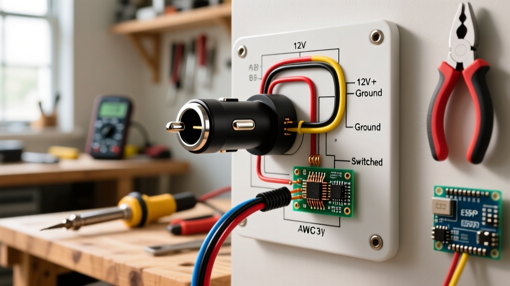
The topology of a 12V accessory circuit is strictly linear. The wiring diagram for a cigarette lighter plug follows this exact path:
- Power Source: 12V Battery Bank or DC Distribution Busbar.
- Overcurrent Protection: 15A ATO/ATC Blade Fuse (placed within 7 inches of the positive source, per ABYC and NFPA 1192 guidelines).
- Switching (Optional): 20A DC-rated rocker switch on the positive leg only.
- Positive Termination: Connects to the center pin at the very back of the socket.
- Negative Termination: Connects to the outer metal shell or designated side-ground tab of the socket.
- Return Path: Negative wire routes back to the DC negative busbar or battery ground.
For a complete understanding of RV-specific electrical safety and grounding requirements, refer to the NFPA 1192 Standard on Recreational Vehicles, which dictates strict separation and fusing rules for 12V DC branch circuits.
Step-by-Step Installation Guide
Step 1: Calculate Load and Select AWG Wire
Most 12V cigarette lighter plugs are physically limited to 10A–15A. The center contact relies on a small spring-loaded button. Pushing 20A through this point contact generates massive heat due to contact resistance. Therefore, we size the circuit for a maximum of 15A.
- Runs under 10 feet (one-way): 14 AWG wire is sufficient (Voltage drop < 3%).
- Runs from 10 to 20 feet: Upgrade to 12 AWG wire to maintain voltage above 11.5V at the socket under load.
Step 2: Panel Preparation and Mounting
Standard automotive sockets require a 21mm (0.83") hole, while heavy-duty marine sockets (like the Marinco) require a 1-1/8" (28.5mm) hole.
Pro-Tip for Gel-Coat and Wood: To prevent 'blowout' or splintering on the back side of your panel, apply blue painter's tape over the drill site. Use a bi-metal hole saw at a low RPM (under 300 RPM) with light, steady pressure. Back the panel with a scrap piece of MDF to ensure a clean exit cut.
Step 3: Terminations and Heat Shrink
Never use bare crimp connectors in a mobile environment. Vibration will cause the wire strands to fret and oxidize.
- Strip exactly 5/16" of insulation from the 12 AWG wire.
- Insert into a 12-10 AWG adhesive-lined heat shrink fork terminal.
- Crimp using a hex-crimp tool (not a standard indent crimper) to deform the barrel into a hexagonal shape, ensuring maximum surface area contact.
- Apply heat with a heat gun at 250°F until the adhesive oozes from the edges, sealing out moisture.
Step 4: Fuse Integration and Grounding
Connect the positive wire to your fuse block. The negative wire must be terminated to a dedicated ground busbar. Never ground a high-draw 12V socket directly to a random sheet metal screw in an RV or vehicle chassis. Chassis grounds are notorious for developing rust and high resistance, which will cause your socket's outer shell to overheat and melt the surrounding paneling.
Common Failure Modes and Edge Cases
Even with a perfect wiring diagram for a cigarette lighter plug, field conditions introduce variables. Here are the most common failure modes observed by mobile technicians:
- Center Pin Melt-Down: Caused by running a 150W inverter (drawing 12.5A+) continuously. The cheap ABS plastic behind the center pin softens at 80°C. Fix: Upgrade to a ceramic-core socket or hardwire the inverter directly to the busbar.
- Plug Ejection: High-current accessories generate heat, which expands the metal plug. If the socket's internal side-springs are weak, the plug will physically push itself out of the socket, breaking the circuit and causing an arc. Fix: Use heavy-duty sockets with dual-ball-detent retention rings.
- Reverse Polarity Damage: If the positive and negative wires are swapped, the accessory will not work, but worse, it can back-feed voltage into sensitive USB charging circuitry built into modern hybrid sockets, instantly frying the internal buck-converter.
Expert Troubleshooting Matrix
If your newly installed 12V outlet is failing to power devices, use this diagnostic matrix before tearing into the walls.
| Symptom | Probable Cause | Diagnostic Action |
|---|---|---|
| Accessory works, but plug is hot to the touch | High contact resistance; weak socket springs or undersized wire. | Measure voltage drop across the socket under load. Replace socket if drop > 0.2V. |
| Blows fuse immediately upon plugging in | Dead short in the accessory or reversed polarity touching chassis. | Test accessory on a known good bench supply. Inspect socket wiring for pinched insulation. |
| Accessory works intermittently when wiggled | Fretting corrosion on wire crimp or worn plug side-contacts. | Pull on wire gently while monitoring continuity. Re-crimp with adhesive heat shrink. |
| Voltage at socket reads 11.2V (Battery is 12.8V) | Severe voltage drop due to undersized wire or poor ground busbar connection. | Measure voltage directly at the battery. If 12.8V, upgrade wire from 14 AWG to 10 AWG. |
For further reading on marine-grade circuit protection and proper DC busbar configurations, the technical guides provided by Blue Sea Systems remain the gold standard for mobile 12V architecture. By adhering strictly to SAE and ABYC principles, your 12V cigarette lighter plug installation will provide reliable, fire-safe power for years of overland and marine adventures.