
The Definitive Electrical Outlet and Plug Wiring Reference
Understanding the relationship between an electrical outlet and plug configurations is the foundation of safe, code-compliant residential and commercial wiring. In North America, the National Electrical Manufacturers Association (NEMA) standardizes these configurations to prevent mismatched voltages and amperages. As of 2026, with the massive proliferation of Level 2 home EV chargers and high-draw smart appliances, knowing exactly how to wire, terminate, and match these devices is more critical than ever.
This wiring diagram reference guide breaks down the most common NEMA receptacle and plug configurations, detailing the exact wire gauges, breaker sizes, and termination torque specifications required by the National Electrical Code (NEC). Whether you are wiring a standard 15-amp bedroom receptacle or a 50-amp EV charging station, this guide provides the actionable specifics you need.
Decoding NEMA Configurations: The Master Matrix
Before stripping any wire, you must verify the NEMA configuration. The alphanumeric code dictates the voltage, amperage, and number of poles/wires. For example, a '5' indicates a 125V/250V grounding configuration, while a '14' indicates a 125V/250V 4-wire grounding setup. Below is the reference matrix for the most frequently installed devices.
| NEMA Config | Voltage | Amperage | Poles / Wires | Min. Copper Wire Gauge (THHN/NM-B) |
|---|---|---|---|---|
| 1-15R / 1-15P | 125V | 15A | 2P / 2W (No Ground) | 14 AWG (Obsolete for new installs) |
| 5-15R / 5-15P | 125V | 15A | 2P / 3W (Grounding) | 14 AWG |
| 5-20R / 5-20P | 125V | 20A | 2P / 3W (Grounding) | 12 AWG |
| 14-30R / 14-30P | 125/250V | 30A | 3P / 4W (Grounding) | 10 AWG |
| 14-50R / 14-50P | 125/250V | 50A | 3P / 4W (Grounding) | 6 AWG (or 4 AWG Aluminum) |
Standard 120V Receptacle Wiring (NEMA 5-15R and 5-20R)
The standard 120V electrical outlet and plug setup relies on a three-wire system: Hot, Neutral, and Ground. The physical wiring behind the yoke remains largely identical for both 15A and 20A devices, though the breaker and wire gauge must scale accordingly.
Terminal Identification and Wire Routing
- Brass Screw (Hot): Connect the black (or red) ungrounded conductor here. This carries the 120V potential from the breaker panel.
- Silver Screw (Neutral): Connect the white grounded conductor here. The neutral completes the circuit back to the panel's neutral bus bar.
- Green Screw (Ground): Connect the bare copper or green insulated equipment grounding conductor (EGC). This provides a low-impedance fault path to trip the breaker in case of a short.
Termination Methods: Side-Wiring vs. Back-Stabbing
A common failure mode in residential wiring is the use of 'back-stab' push-in terminals. While UL-listed, these spring-loaded contacts are notorious for loosening over time due to thermal expansion and contraction, leading to high-resistance arcing. For a permanent, fire-safe installation, always use side-wiring (wrapping the wire clockwise around the screw) or screw-clamp back-wiring (where tightening the screw clamps a metal plate over the wire inserted into the back hole).
Pro Tip: When side-wiring, strip exactly 3/4 inch of insulation. Hook the wire around the screw so that the insulation sits flush against the washer, and no bare copper is exposed outside the terminal pad. This prevents accidental shorting if the device is pushed tightly into the junction box.
High-Voltage 240V Wiring (NEMA 14-30R and 14-50R)
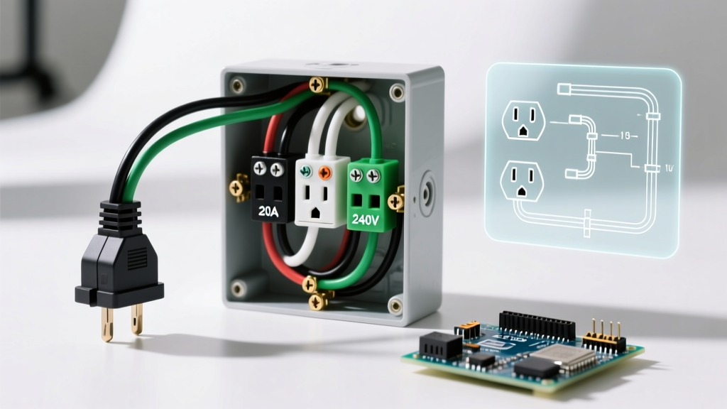
Wiring a 240V electrical outlet and plug configuration requires a 4-wire setup to provide both 240V for heavy loads and 120V for control boards or timers. This is standard for electric dryers (14-30) and ranges or EV chargers (14-50).
The 4-Wire Diagram Breakdown
- X and Y Terminals (Brass): Connect the two hot legs (typically Black and Red). Each leg carries 120V relative to neutral, and 240V relative to each other.
- W Terminal (Silver/White): Connect the white neutral wire. This is critical for appliances that require 120V for internal electronics.
- G Terminal (Green): Connect the bare ground wire to the grounding bus or grounding rod system.
Crucial Code Note: Prior to the 1996 NEC, 3-wire setups (combining neutral and ground) were allowed for dryers and ranges. Today, NEC Article 250.140 strictly prohibits using the neutral as an equipment ground for new installations. You must run a dedicated 4-wire cable (e.g., 10/3 NM-B for 30A or 6/3 NM-B for 50A).
The 2026 EV Charging Edge Case: NEMA 14-50R Failures
As electric vehicle adoption surges, the NEMA 14-50 electrical outlet and plug combination has become the de facto standard for portable Level 2 EV chargers. However, this has introduced a massive, widespread failure mode in DIY and even some professional installations.
Standard residential 14-50R receptacles (which typically cost between $10 and $15) are engineered and tested for intermittent 50A loads, such as an electric range that cycles its heating elements on and off. EV chargers, however, pull a continuous load of 32A to 40A for 4 to 10 hours at a time. Under NEC Article 210.20(A), continuous loads require the branch circuit to be rated at 125% of the load. Therefore, a 40A EV charger requires a 50A breaker.
When a continuous 40A load is applied to a cheap residential 14-50R receptacle, the internal brass contacts fatigue, loosen, and generate immense heat, frequently resulting in melted plastic yokes and fire hazards. The Solution: If you must use a receptacle for EV charging, install a commercial-grade, industrial-specification receptacle like the Hubbell 9450A or Bryant 9450FR (priced around $85 to $120). These feature massive, high-tension brass contacts designed specifically for continuous high-amperage draw. Better yet, hardwire the EV charger directly to a junction box to eliminate the receptacle failure point entirely.
NEC Torque Specifications and Tooling
One of the most heavily enforced updates in recent NEC cycles is NEC 110.14(D), which mandates that all electrical connections be torqued to the manufacturer's specified values using a calibrated tool. 'Hand-tight' is no longer a legally defensible standard for passing inspection.
For most standard 15A and 20A duplex receptacles (such as the Leviton 5262 or Eaton TR270), the manufacturer specifies a torque of 14 in-lbs (1.6 Nm). For larger 14-50R receptacles, the torque requirement often jumps to 35 to 45 in-lbs depending on the brand. Under-tightening causes micro-arcing and thermal runaway; over-tightening strips the brass threads or fractures the copper conductor inside the insulation.
To comply, electricians must use a dedicated torque screwdriver, such as the Klein Tools 69030 or the Wiha 28502, which are pre-calibrated or adjustable to these exact in-lb specifications. Standard multi-bit screwdrivers with magnetic tips cannot provide measurable torque feedback.
Troubleshooting Common Outlet and Plug Mismatches
When diagnosing a failing circuit or replacing a damaged plug, verify that the plug configuration perfectly matches the receptacle. A common hazard occurs when users file down the neutral prong on a 15A plug to force it into a 20A T-slot receptacle, or vice versa. While a 15A plug is legally allowed to be inserted into a 20A receptacle (as the 20A circuit can safely handle the 15A load), modifying the physical plug blades violates OSHA and NEC listing requirements, instantly voiding the UL certification and creating a severe shock hazard.
Always inspect the plug blades for pitting or black carbon deposits. If a plug shows arcing marks, the corresponding receptacle's internal wipers are likely worn and no longer providing adequate clamping force. In these cases, both the plug cap and the receptacle must be replaced simultaneously to ensure a low-resistance, safe connection.