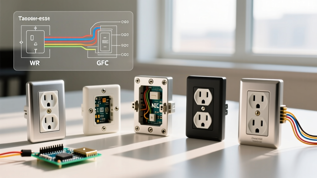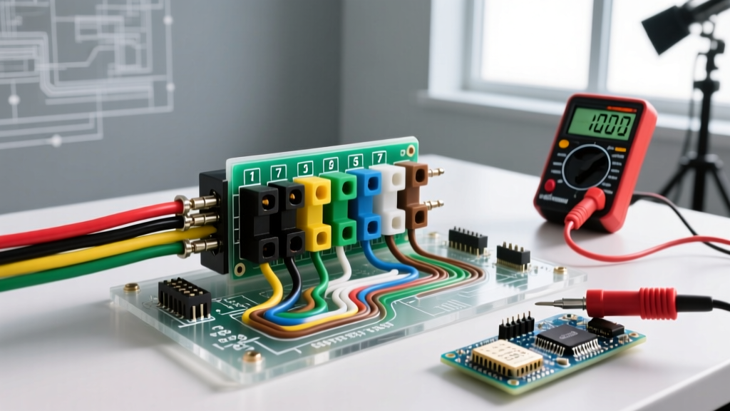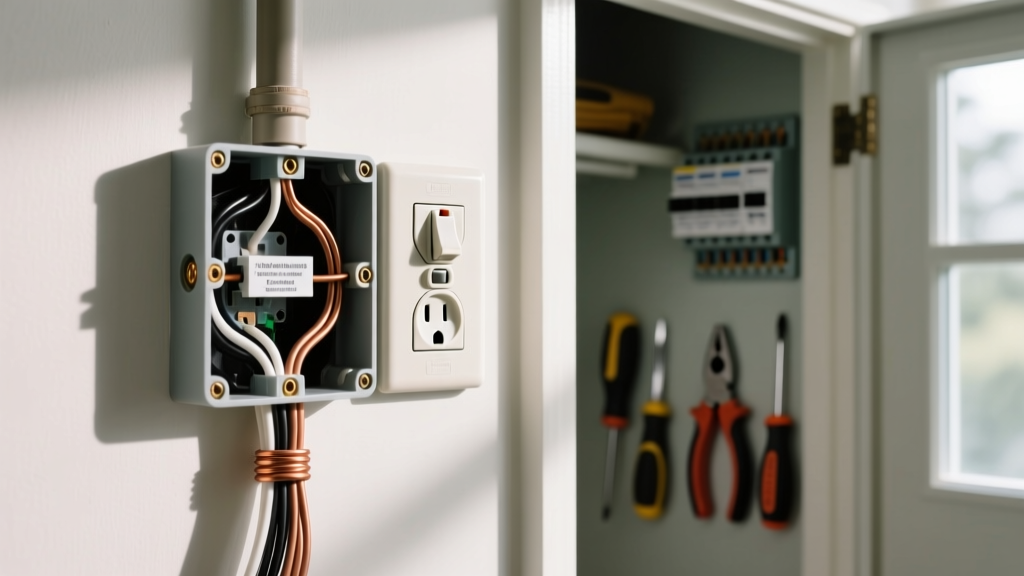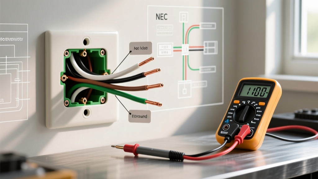

The Reality of Outlet Wiring: Why You Cannot Trust Colors
When inspecting or upgrading residential and commercial receptacles, assuming that electrical outlet wire colors strictly follow code is a dangerous mistake. While the National Electrical Code (NEC) mandates specific color coding for conductors, decades of unpermitted DIY repairs, legacy cloth wiring, and careless contractor work mean that the wires behind your wall plates often tell a different story. According to the Electrical Safety Foundation International (ESFI), electrical malfunctions cause tens of thousands of home fires annually, many stemming from misidentified conductors and reversed polarities.
As an inspector or advanced DIYer, your objective is never to rely on visual color identification alone. Instead, you must use a systematic testing protocol to verify the actual function of each conductor. This guide details the NEC standards for wire colors, the professional tools required for verification, and a step-by-step testing methodology to uncover hidden hazards like bootleg grounds and switched neutrals.
Standard NEC Electrical Outlet Wire Colors
Under NFPA 70 (the National Electrical Code), specific colors are reserved for specific functions to ensure uniformity and safety across installations. Article 200 covers the use and identification of grounded (neutral) conductors, while Article 250 governs grounding and bonding.
| Conductor Function | Standard NEC Color (120V/240V) | Alternate / Commercial Colors | Receptacle Terminal |
|---|---|---|---|
| Hot (Line 1) | Black | Red, Blue (3-phase), Brown | Brass (Gold) |
| Hot (Line 2 / 240V) | Red | Black (with phase tape) | Brass (Gold) |
| Neutral (Grounded) | White | Gray (commercial/industrial) | Silver |
| Ground (Equipment) | Bare Copper or Green | Green with Yellow Stripe | Green |
Inspector's Note: White or gray wires can legally be used as ungrounded (hot) conductors in switch loops or 240V appliances, provided they are permanently re-identified with black tape or paint at both ends. If you see a white wire connected to a brass terminal without re-identification, you have found a code violation.
Essential Testing Gear for 2026 Inspections
To properly verify electrical outlet wire colors and their corresponding functions, you need a tiered approach to testing. Relying on a single tool leaves blind spots in your inspection.
- Non-Contact Voltage Tester (NCVT): The Gardner Bender GPT-4001 or Fluke VoltAlert. Used for initial sweep to detect live voltage through insulation without exposing bare wire.
- Receptacle Tester: The Klein Tools RT210 (~$16). A crucial first-line diagnostic tool that uses an LED matrix to instantly flag reverse polarity, open grounds, and open neutrals.
- True RMS Digital Multimeter: The Fluke 117 (~$210) or Klein Tools MM700. Essential for measuring exact voltage potentials, identifying phantom voltages, and measuring Neutral-to-Ground impedance.
Step-by-Step Inspection and Testing Protocol
Follow this exact sequence to safely map and verify the conductors inside a standard 15A or 20A duplex receptacle. Always adhere to OSHA electrical safety guidelines regarding PPE and safe work practices when dealing with energized panels.
Phase 1: De-energized Visual Inspection
Before applying power, turn off the circuit breaker and verify it is dead using your NCVT. Remove the receptacle cover and pull the yoke out of the junction box.
- Check for Re-identification: Look for white wires wrapped in black electrical tape. This indicates a switch loop or a 240V setup where the white wire is acting as a hot leg.
- Inspect the Grounding Path: Ensure the bare copper or green wire is securely fastened to the green grounding screw and, if present, pigtailed to a metal junction box.
- Look for 'Bootleg' Jumpers: A severe hazard where a previous worker ran a jumper wire from the neutral (silver) terminal to the ground (green) terminal to trick a standard receptacle tester into showing a false 'correct' reading. If you see this, remove it immediately.
Phase 2: Live Voltage Verification
Restore power at the breaker. Keep your hands clear of bare terminals and use your True RMS multimeter set to AC Voltage (V~).
- Hot to Neutral (Black to White): Insert probes into the slot corresponding to the brass and silver terminals. You should read between 114V and 126V (the standard 120V +/- 5% tolerance).
- Hot to Ground (Black to Bare/Green): Measure from the brass terminal to the green terminal. This should read identically to your Hot-Neutral reading (114V - 126V).
- Neutral to Ground (White to Bare/Green): This is the most critical test for circuit health. You should read 0V to 2V.
Phase 3: Interpreting Neutral-to-Ground Potential
If your Neutral-to-Ground reading exceeds 3V, you have a structural issue in the circuit. A high Neutral-to-Ground voltage indicates either an overloaded shared neutral (common in older multi-wire branch circuits), a loose neutral connection upstream causing voltage drop, or an undersized wire gauge for the distance of the run. This potential difference can cause sensitive electronics to fail prematurely and creates a shock hazard if the ground path is severed.
Diagnosing Common Wiring Faults and Edge Cases
When the physical wire colors do not match the multimeter readings, you have uncovered a fault. Here is how to diagnose the most common anomalies found during outlet inspections.
1. Reverse Polarity
The Symptom: Your Klein RT210 receptacle tester shows the 'Reverse Polarity' LED pattern. Your multimeter reads 120V, but the hot wire (black) is connected to the silver terminal, and the neutral (white) is connected to the brass terminal.
The Hazard: The internal switch of a lamp plugged into this outlet will only break the neutral path. The bulb socket remains fully energized at 120V even when the lamp is turned off, posing a severe shock risk if someone touches the socket threads while changing a bulb.
The Fix: De-energize the circuit, swap the black and white wires to their respective brass and silver terminals, and torque the screws to the manufacturer's specification (usually 12-14 in-lbs for standard 15A/20A receptacles).
2. The Switched Neutral
The Symptom: An outlet is controlled by a wall switch, but testing reveals the hot wire is always live, while the switch is actually interrupting the white neutral wire.
The Hazard: This is a legacy wiring method banned decades ago. Devices plugged in will turn off, but their internal components remain energized at line voltage.
The Fix: This requires rewiring the switch loop at the junction box or switch location to ensure the black (hot) conductor is the one being broken by the switch mechanism.
3. Open Ground with Phantom Voltage
The Symptom: A digital multimeter reads 60V to 90V between Hot and Ground, but a solenoid-style voltage tester (wiggy) reads 0V. The receptacle tester indicates an 'Open Ground'.
The Hazard: Digital multimeters have high input impedance (often 10 Megohms), meaning they can detect capacitive coupling (phantom voltage) from adjacent live wires in the same cable sheath. There is no actual equipment grounding conductor present.
The Fix: You must either run a new equipment grounding conductor back to the panel, or replace the standard receptacle with a GFCI receptacle. Under NEC Article 406.4(D)(2), a GFCI can replace an ungrounded receptacle, provided it is labeled with the included 'No Equipment Ground' sticker.
Summary Checklist for Inspectors
Never trust the color of the wire insulation at face value. A rigorous inspection relies on empirical data gathered through proper testing equipment. By combining a visual inspection for bootleg grounds and improper re-identification with precise True RMS multimeter measurements of Hot-Neutral and Neutral-Ground potentials, you ensure the outlet is not only functional, but genuinely safe for the end-user.