
Why Upgrading Your Electrical Outlets is Critical in 2026
Learning how to put in a new electrical outlet is one of the most foundational DIY electrical skills, but simply swapping a broken faceplate for a new one is no longer sufficient. Modern electrical codes and safety standards demand more. If you are replacing an outlet in an older home, you are likely dealing with degraded thermoplastic, loose backstabbed connections, or a complete lack of equipment grounding. According to the National Fire Protection Association (NFPA), electrical failures or malfunctions are consistently among the leading causes of home structure fires, often originating at the receptacle termination points due to high-resistance connections.
This upgrade and replacement guide moves beyond basic wiring diagrams. We will cover the diagnostic steps required before you touch a screwdriver, the exact materials needed for code-compliant upgrades, and the advanced edge cases—like bootleg grounds and aluminum wiring—that turn a simple swap into a hazardous failure point.
Phase 1: The Pre-Swap Diagnostic Assessment
Before cutting power, you must understand the existing circuit's topology and health. Do not blindly rip out the old receptacle.
- Test for Grounding Integrity: Use a digital multimeter (DMM) or an advanced circuit analyzer like the Klein Tools ET45. Measure Hot-to-Neutral (should be ~120V), Hot-to-Ground (~120V), and Neutral-to-Ground (should be <2V). If Neutral-to-Ground reads 0.0V but you see no bare copper wire in the box, you may have a "bootleg ground" (a dangerous jumper wire between neutral and ground).
- Identify Wire Gauge and Material: Shine a flashlight into the electrical box. Are the conductors copper or aluminum? Is the wire 14 AWG (15-Amp circuit) or 12 AWG (20-Amp circuit)? You must match the new receptacle's ampacity rating to the breaker and wire gauge.
- Check Box Fill Capacity: Per NEC Article 314.16, electrical boxes have maximum volume limits. A standard 15A receptacle counts as two conductor allowances. If you are upgrading to a bulkier GFCI or smart outlet in a shallow 12-cubic-inch box, you may violate box fill rules, causing wire crushing and short circuits.
Phase 2: Material Selection Matrix
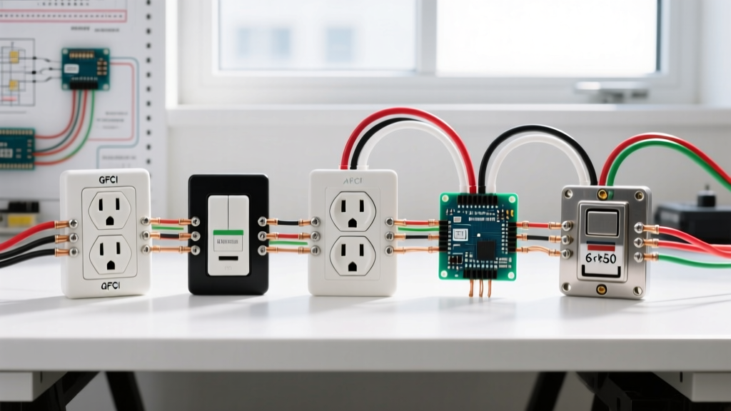
Not all receptacles are built equally. The Electrical Safety Foundation International (ESFI) heavily advocates for Tamper-Resistant Receptacles (TRRs) in all residential upgrades to prevent childhood shock injuries. Below is a comparison of the most common upgrade paths.
| Receptacle Type | Recommended Model (2026) | Avg. Cost | Best Application |
|---|---|---|---|
| Standard 15A TRR | Leviton T5325-W | $3.25 | Bedrooms, living rooms, hallways |
| Commercial 20A TRR | Pass & Seymour 5266-X | $6.50 | Kitchens, bathrooms, high-draw appliance zones |
| 15A GFCI TRR | Leviton GFNL1-W | $18.50 | Garages, outdoors, unfinished basements, near water |
| CO/ALR Rated (Aluminum) | Leviton 1227-SW | $9.00 | Homes with 1970s aluminum branch wiring |
Phase 3: The 5-Step Replacement Protocol
Step 1: Lockout, Tagout, and Verify
Turn off the circuit breaker and apply a physical lockout tag if you share the home with others. Verify the power is dead using a non-contact voltage tester (NCVT), followed by a multi-meter test across the hot and neutral slots. Never rely solely on an NCVT, as phantom voltages or shielded wires can yield false negatives.
Step 2: Extract and Inspect the Old Device
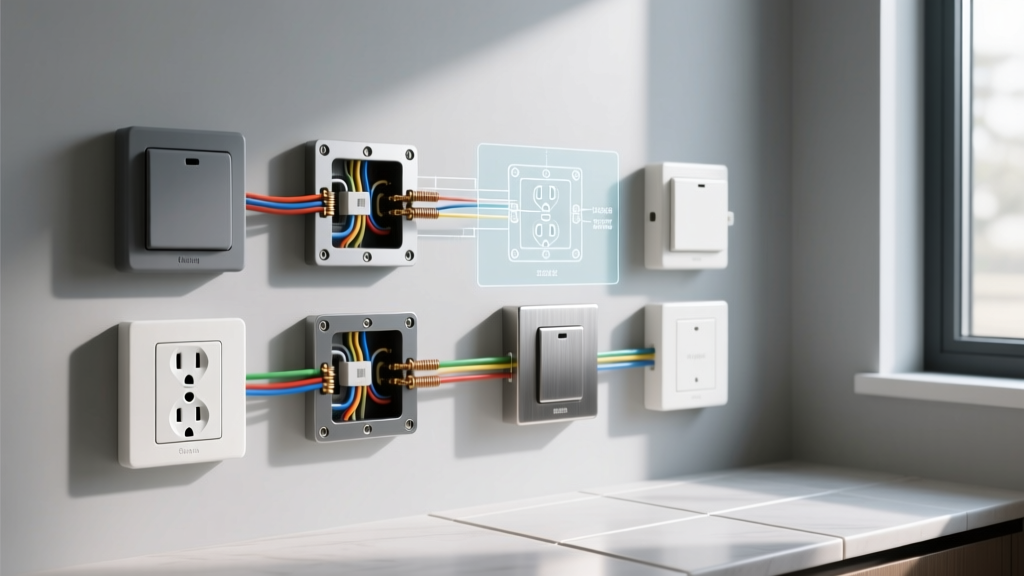
Remove the faceplate and the top/bottom mounting screws. Gently pull the receptacle out of the box. Inspect the existing wiring terminations. If the wires are pushed into the back of the device (known as "backstabbing" or push-in terminals), this is a primary failure mode. Backstabbed connections rely on a tiny internal spring that loosens over time due to thermal expansion and contraction, leading to arcing and melted plastic. Your new installation will strictly use side-wiring (screw terminals).
Step 3: Prep and Strip the Conductors
Cut off the old, oxidized, or nicked copper ends using wire cutters. Using a precision wire stripper (like the Klein Tools 11055), strip exactly 5/8-inch of insulation from the black (hot), white (neutral), and bare (ground) wires. Crucial: Do not nick the copper conductor while stripping. A nicked wire creates a mechanical weak point that will snap when folded into the box or cause a localized hot-spot under load.
Step 4: Terminate and Torque
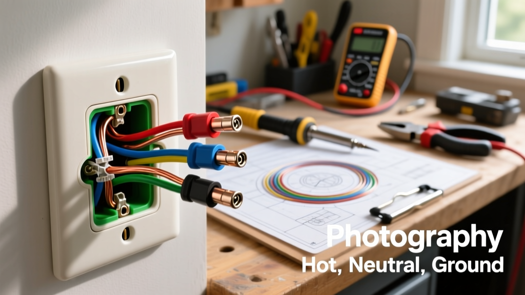
Form a "J-hook" at the end of each stripped wire using needle-nose pliers. Loop the wire clockwise around the corresponding brass (hot), silver (neutral), and green (ground) screws. This ensures that tightening the screw pulls the wire loop tighter rather than pushing it out.
Tighten the screws firmly. For true E-E-A-T compliance and fire prevention, use a calibrated torque screwdriver. Standard 15A and 20A receptacles typically require 14 in-lbs (inch-pounds) of torque. Overtightening strips the screw head; undertightening creates high-resistance connections that generate catastrophic heat.
Step 5: Dress the Box and Test
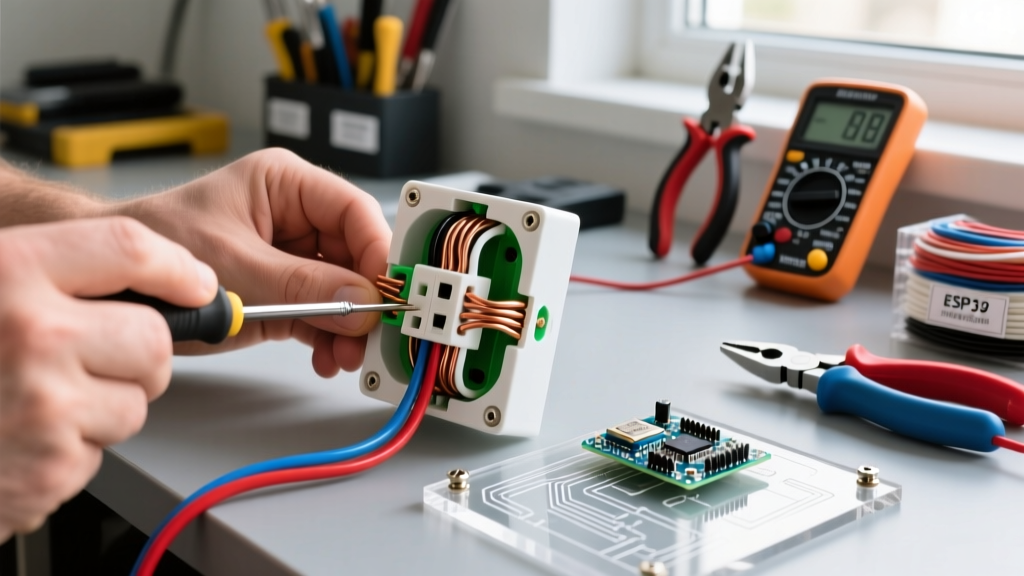
Carefully fold the wires into the back of the box. Push the ground wires in first, followed by the neutrals, and finally the hots. This accordion-style folding prevents pinching the hot wire against the metal box or the device yoke. Mount the receptacle, ensuring it sits flush and level. Restore power and test with a 3-light receptacle tester to confirm correct polarity and grounding.
Phase 4: Edge Cases & Advanced Troubleshooting
The "Bootleg Ground" Trap
Warning: A bootleg ground is a deceptive and illegal wiring method where a jumper wire connects the neutral terminal to the ground screw, tricking standard 3-light testers into reading "Correct Wiring." The Consumer Product Safety Commission (CPSC) warns that this creates a severe shock hazard if a neutral fault occurs, as the appliance chassis becomes energized.
The Fix: If you discover a bootleg ground, remove the jumper. If there is no true equipment grounding conductor (EGC) available in the box, the NEC allows you to install a GFCI receptacle as a replacement. The GFCI will protect the user from shock even without a ground wire. You must apply the included "No Equipment Ground" and "GFCI Protected" stickers to the faceplate to remain code-compliant.
Dealing with Aluminum Wiring
If your home was built between 1965 and 1973, you may have aluminum branch circuit wiring. Aluminum expands and contracts at a different rate than copper and is prone to oxidation, which increases resistance. You cannot use standard copper-rated (CU-only) receptacles. You must purchase receptacles specifically marked CO/ALR. Furthermore, you must apply an antioxidant compound (like Noalox) to the stripped aluminum wire before terminating it under the screw to prevent future oxidation.
Shallow Box Upgrades
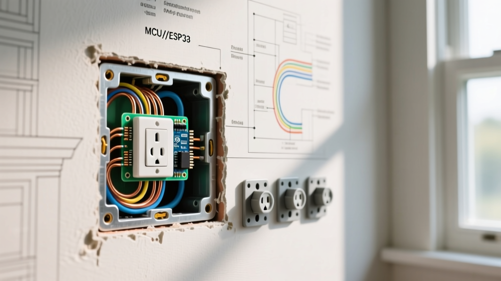
If you are upgrading to a GFCI or a smart outlet with built-in Wi-Fi/Zigbee relays, the physical depth of the device often exceeds the capacity of older 14-cubic-inch shallow boxes. If the wires are aggressively crushed to make the device fit, the insulation will eventually fail. Upgrade the box to a deep "Old Work" retrofit box, such as the Carlon B618R (18 cubic inches), which provides ample room for modern, bulky devices and satisfies NEC box fill calculations.
Final Thoughts on Outlet Upgrades
Understanding how to put in a new electrical outlet is about more than just restoring power to a room; it is an opportunity to bring your home's infrastructure up to modern safety standards. By abandoning backstabbed terminations, utilizing torque-calibrated tools, and installing TRR or GFCI devices where appropriate, you eliminate the most common ignition sources for residential electrical fires. Always prioritize diagnostic testing before demolition, and never hesitate to consult a licensed electrician if you encounter ungrounded feeder cables, scorched wire insulation, or aluminum wiring that requires specialized pigtailing.