
Why Legacy Diagrams Fail: The NEC 404.2(C) Neutral Mandate
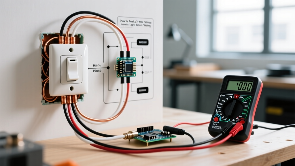
If you are searching for a wiring diagram for dimmer light switch installations, you must first discard any guides published before the 2011 National Electrical Code (NEC) cycle. Legacy diagrams typically illustrate a simple series loop: a line (hot) wire, a load wire, and a ground. While this worked for incandescent bulbs and basic triac-based rheostats, it is fundamentally non-compliant and unsafe for modern solid-state and smart dimmers.
Under NEC Article 404.2(C), a neutral conductor is now required at nearly all switch boxes. Modern dimmers—such as the Lutron Maestro MACL-153M (retailing around $28–$32 in 2026) or smart hubs like the Lutron Caseta PD-6WCL—contain internal microprocessors and LEDs that require a continuous 120V circuit to operate, even when the lights are turned off. Without a neutral wire, these devices will attempt to draw trickle current through the load (the light bulbs), causing LED ghosting, flickering, or premature failure of the dimmer's internal capacitor.
Safety Directive: Never rely on the bare copper or green grounding wire as a substitute for a neutral (white) wire. Doing so creates a parallel path for neutral current on the equipment grounding conductor, violating NEC 250.142 and creating a severe shock and fire hazard.
Step-by-Step: Executing the Modern Wiring Diagram for Dimmer Light Switch Setups
Before touching a single wire, verify the circuit is dead. Use a non-contact voltage tester (NCVT), such as the Klein Tools NCVT-3 ($25), to test the existing switch terminals and the box interior. Once verified, follow this precise termination sequence to ensure mechanical and electrical integrity.
Phase 1: Wire Preparation and Identification
- Identify the Line and Load: In a single-pole setup, separate the two black (or red) wires. Use a voltage sniffer with the breaker temporarily on and wires safely separated to identify the 'Line' (always hot) and 'Load' (switched hot). Mark the Line wire with black electrical tape.
- Locate the Neutral Bundle: Find the bundle of white wires tucked in the back of the box. Do not use a white wire that is part of a switch loop unless it has been re-identified with black tape at both ends per NEC 200.7(C)(2).
- Strip to Exact Specifications: Dimmer manufacturers are highly specific about strip lengths. For rear-insert push-in terminals (common on Leviton Decora models), strip exactly 7/16 inch. For side-screw terminal loops, strip 3/4 inch to ensure the wire wraps fully around the screw without exposing bare copper outside the terminal.
Phase 2: Termination Sequence
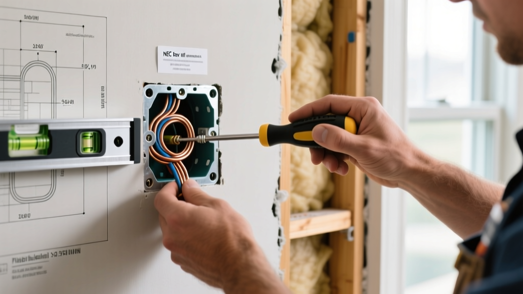
- Ground First: Connect the bare copper or green pigtail from the dimmer to the box's grounding screw or ground wire bundle. Use an Ideal 72B Tan Wire-Nut for 14 AWG wires or an Ideal 74B Yellow for 12 AWG.
- Neutral Connection: Add the dimmer's white (or blue, depending on brand) neutral wire to the existing neutral bundle. You may need to upgrade to a larger wire nut (e.g., Ideal 73B Orange) to accommodate the extra wire.
- Line and Load: Connect the dimmer's black (Line) wire to your identified always-hot source, and the dimmer's red or blue (Load) wire to the wire leading to the light fixture.
- Torque Verification: Tighten terminal screws firmly. While residential dimmers rarely specify exact torque values on the device, aiming for 14 in-lbs ensures the wire will not loosen under thermal expansion cycles.
NEC 314.16 Box Fill Calculations: Avoiding Thermal and Code Violations
The most common code violation when upgrading to a dimmer is ignoring box fill capacity. Dimmers are significantly deeper than standard toggle switches, generating more heat and requiring more physical volume. According to NEC Article 314.16, you must calculate the cubic inch capacity required by all wires, clamps, and devices in the box.
A standard single-pole dimmer counts as two current-carrying conductors for box fill calculations. Below is the 2026 reference matrix for standard residential wiring:
| Wire Gauge | Cubic Inches per Wire | Dimmer Device Allowance (2x) | Grounding Wire Allowance (1x) | Total Volume for 1 Dimmer + 2 Cables (Line/Load) |
|---|---|---|---|---|
| 14 AWG | 2.0 cu in. | 4.0 cu in. | 2.0 cu in. | 14.0 cu in. minimum |
| 12 AWG | 2.25 cu in. | 4.5 cu in. | 2.25 cu in. | 15.75 cu in. minimum |
Note: If your existing single-gang plastic nail-on box is only 12 cubic inches (common in 1990s construction), you must replace it with a deep 22.5 cubic inch 'old work' box (e.g., Carlon B618R) to safely and legally install a modern dimmer.
Dimmer Compatibility Matrix: Preventing Fire Hazards and Flicker
Matching the dimmer to the load type is a critical safety step. Using an incandescent-only dimmer on LED fixtures can cause the dimmer's triac to overheat, potentially melting the faceplate or starting an electrical fire. Always consult the U.S. Department of Energy's Solid-State Lighting guidelines to understand how LED drivers interact with phase-cut dimmers.
| Dimmer Model (2026 Market) | Designed Load Type | Max LED Capacity | Max Incandescent Capacity | Neutral Required? |
|---|---|---|---|---|
| Lutron Maestro MACL-153M | LED / CFL / Incandescent | 150W (approx. 15 bulbs) | 600W | No (but recommended) |
| Leviton Decora DSL06 | LED / CFL / Incandescent | 150W | 600W | Yes (Mandatory) |
| Lutron Diva DV-600P | Incandescent / Halogen ONLY | DO NOT USE | 600W | No |
| Lutron Caseta PD-6WCL | Smart LED / Incandescent | 100W | 250W | No (Draws via load) |
Heat Sink Derating: The Hidden Ganging Penalty
Dimmers dissipate excess voltage as heat through aluminum fins located on the sides of the metal yoke. When installing a single dimmer in a single-gang box, leave all fins intact. However, if you are 'ganging' multiple dimmers side-by-side in a multi-gang box, you must snap off the fins that touch adjacent devices to fit them into the faceplate.
The Derating Penalty: Removing these fins reduces the dimmer's heat dissipation capacity. For example, the Lutron MACL-153M is rated for 150W of LED load when fully finned. If you remove one side of fins, the maximum safe LED load drops to 100W. If you remove both sides (ganging three dimmers together), the capacity drops to 60W. Exceeding these derated limits will trigger the dimmer's internal thermal protection, causing the lights to shut off randomly or cycle on and off until the device cools.
Edge Case Troubleshooting: Ghosting and Minimum Load
Even with a perfect wiring diagram for dimmer light switch execution, LED edge cases occur. Here is how to resolve them like a professional:
- LED Ghosting (Lights stay dimly lit when off): This happens when a smart dimmer or a dimmer without a neutral wire leaks a few milliamps of current through the circuit to power its internal Wi-Fi radio or LED locator. If your LED bulbs have a low minimum threshold, they will glow. Fix: Install a Lutron LUT-MLC capacitor (approx. $12) across the hot and neutral at the light fixture, not at the switch box. This provides a bypass path for the trickle current.
- Drop-Out (Lights turn off before the slider reaches zero): LEDs require a minimum voltage to keep their internal drivers engaged. If the dimmer's low-end trim is set too low, the bulbs will simply shut off at 15% brightness. Fix: Use the dimmer's hidden calibration mode (usually holding the down arrow for 6 seconds on Lutron models) to raise the low-end trim until the bulbs remain stable at the lowest desired setting.
Authoritative References & Further Reading
Electrical safety requires adherence to the latest codes and manufacturer specifications. For further validation of the practices outlined in this guide, consult the following authoritative resources:
- National Fire Protection Association (NFPA) - Electrical Safety Guidelines: Comprehensive overview of residential electrical hazards and NEC compliance.
- U.S. Department of Energy - Solid-State Lighting: Technical data on LED driver compatibility and phase-cut dimming physics.
- Lutron Technical Support & Advanced FAQ: Manufacturer-specific wiring diagrams, derating charts, and LUT-MLC installation guides.