
Decoding Electrical Wiring Diagrams for Light Switch Outlet Combos
When interpreting an electrical wiring diagram for a light switch and outlet combo (industry-standard terminology refers to these as 'combination devices' or 'switch/receptacles'), understanding the schematic symbols is only the first step. The true mark of an expert electrician or advanced DIYer lies in applying the latest National Electrical Code (NEC) mandates to the physical installation. Whether you are installing a standard Leviton 5241 (15A, 125V single-pole switch with a duplex receptacle) or a heavy-duty Cooper Wiring Devices 2925, the diagram on the back of the box does not tell the whole story regarding safety and compliance.
According to the National Fire Protection Association (NFPA), improper wiring of combination devices accounts for a significant percentage of residential electrical fires related to receptacle failures. This guide breaks down the critical code compliance metrics, box fill calculations, and exact wiring procedures required for a safe, legal installation.
The Anatomy of a Combo Device Schematic
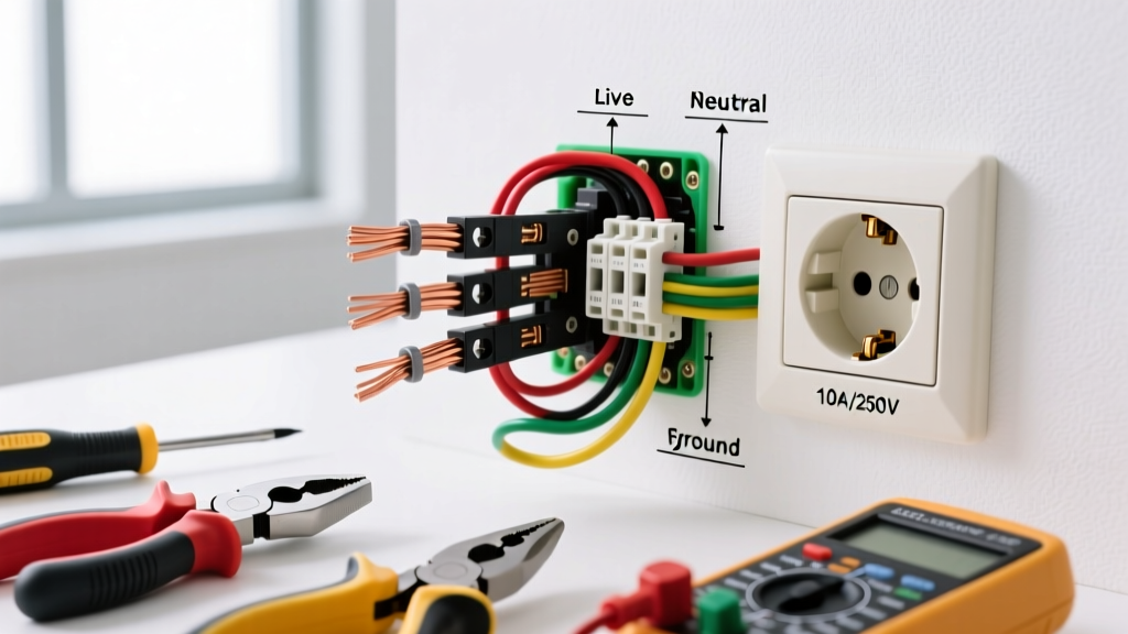
Standard electrical wiring diagrams for light switch and outlet combos typically depict two distinct internal circuits sharing a single yoke. The schematic will show:
- Line (Hot) Input: Usually designated by a brass-colored screw. This brings 120V AC from the breaker panel.
- Load (Switched) Output: A second brass screw that sends power to the light fixture only when the toggle is actuated.
- Neutral Bus: Silver-colored screws that complete the circuit for both the receptacle and the downstream light fixture.
- Grounding Terminal: A green hex screw bonded directly to the metal mounting yoke.
Code Alert (NEC 404.2(C)): Modern electrical wiring diagrams for light switches often require a neutral wire at the switch box. If you are upgrading an older home with a legacy 'switch loop' (where only a hot and a switched hot were run to the box), you cannot legally install a smart combo switch or any device requiring a neutral for internal LED indicators without pulling a new 3-wire (12/3 or 14/3) cable.
NEC Box Fill Calculations: The Most Ignored Diagram Metric
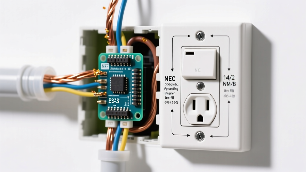
An electrical wiring diagram tells you how to connect the wires, but it does not tell you if the wires will legally fit inside the electrical box. Cramming too many wires into a standard single-gang box causes excessive heat buildup and physical damage to the wire insulation. Under NEC Article 314.16, you must perform a box fill calculation before installing any switch/outlet combo.
For a standard 15A circuit using 14 AWG wire, each current-carrying conductor requires 2.0 cubic inches of space. For a 20A circuit using 12 AWG wire, the requirement jumps to 2.25 cubic inches per conductor.
Box Fill Allowance Matrix for Combo Devices
| Item in Box | NEC Multiplier | Volume (14 AWG / 2.0 cu in) | Volume (12 AWG / 2.25 cu in) |
|---|---|---|---|
| Hot (Line) Wire | 1x | 2.0 cu in | 2.25 cu in |
| Neutral Wire | 1x | 2.0 cu in | 2.25 cu in |
| Switched Hot (Load) | 1x | 2.0 cu in | 2.25 cu in |
| Equipment Ground | 1x (Total for all grounds) | 2.0 cu in | 2.25 cu in |
| Internal Clamps | 1x (Total for all clamps) | 2.0 cu in | 2.25 cu in |
| Device Yoke (The Combo Switch) | 2x | 4.0 cu in | 4.50 cu in |
| Total Minimum Box Volume | N/A | 14.0 cu in | 18.0 cu in |
Pro Tip: A standard single-gang 'old work' drywall box (like the Arlington Industries BE1) typically offers only 14 to 18 cubic inches. If you are wiring a 12 AWG 20A combo device with clamps and multiple grounds, you must upgrade to a deep single-gang box (22+ cu in) or a double-gang box to remain code-compliant.
Step-by-Step Code-Compliant Wiring Execution
Following the electrical wiring diagram is insufficient if the physical execution violates safety standards. Adhere to this precise workflow to ensure compliance with OSHA electrical safety guidelines and the NEC.
- Verify Circuit Capacity and GFCI/AFCI Mandates: Before touching a wire, identify the room. Under NEC 210.12 and 210.8, bedrooms, living rooms, and hallways require Arc-Fault Circuit Interrupter (AFCI) protection, while kitchens, bathrooms, garages, and outdoor locations require Ground-Fault Circuit Interrupter (GFCI) protection. If the breaker is not an AFCI/GFCI combo, the first device in the circuit must be a GFCI receptacle, and your combo switch must be wired to the 'LOAD' terminals of that GFCI.
- Strip to Exact Gauge Specifications: Do not guess the wire strip length. For standard side-wiring on a 15A Leviton combo device, strip exactly 3/4 inch of insulation. For back-wiring (inserting the wire into the rear clamp), strip exactly 5/8 inch. Exposed copper outside the terminal is a severe shock hazard and an immediate inspection failure.
- Form the Shepherd's Hook Correctly: When using side terminals, loop the wire clockwise around the brass or silver screw. This ensures that tightening the screw pulls the loop tighter rather than pushing it out. The insulation should rest flush against the steel washer—no bare copper should be visible outside the terminal plate.
- Torque to Manufacturer Specifications: This is the most frequently failed inspection point in modern electrical work. NEC 110.14(D) requires that terminals be tightened to the manufacturer's specified torque. For most residential 15A and 20A combo devices, this is between 12 and 14 inch-pounds. Use a calibrated torque screwdriver (such as the Klein Tools 32308 or Wiha 645P) to secure the connections. Hand-tightening leads to arcing and thermal expansion failures over time.
- Isolate the Grounding Pigtail: Never 'daisy-chain' the bare copper ground wire through the green screw on the device yoke to feed downstream devices. NEC 250.148 requires that the equipment grounding conductor be spliced with a wire nut or push-in connector (like a Wago 221-3), with a dedicated pigtail run to the combo device's green terminal.
Critical Code Violations to Avoid
When reviewing electrical wiring diagrams for light switch and outlet combinations, DIYers frequently make the following dangerous errors:
- The Bootleg Ground: Connecting a jumper wire from the neutral (silver) screw to the ground (green) screw to trick a receptacle tester into showing a 'correct' wiring reading. This is a lethal violation. If the neutral wire ever disconnects upstream, the metal faceplate and any plugged-in appliance chassis will become energized at 120V.
- Breaking the Hot Fin Unnecessarily: Combo devices feature a brass break-off fin on the hot side. This fin is only meant to be removed if you are wiring a 'split receptacle' (where one half of the outlet is always hot, and the other half is switched). If you are simply feeding power through the outlet to the switch, the fin must remain intact. Removing it without a specific schematic requirement causes a dead short when the device is inserted into the box.
- Multi-Wire Branch Circuit (MWBC) Neutral Sharing: If your switch box is fed by a 12/3 or 14/3 cable sharing a single neutral between two hot legs (Red and Black), NEC 240.15(B)(1) mandates that the two breakers be tied together with an approved handle tie or be a single double-pole breaker. Failing to do this means an electrician could turn off one breaker to work on the outlet, while the other leg remains live on the shared neutral, creating a fatal shock hazard.
Frequently Asked Questions (FAQ)
Can I wire the outlet to be controlled by the switch on a combo device?
Yes, but it requires a specific wiring configuration. You must connect the incoming Line (Hot) to the switch's Line terminal, and then run a short jumper wire from the switch's Load terminal to the receptacle's Hot (brass) terminal. However, for high-draw appliances, this is generally discouraged as the internal switch contacts on a standard 15A combo device are typically rated only for 1/2 HP or standard lighting loads, not continuous heavy appliance draws.
Do I need a GFCI combo switch in my bathroom?
Yes. According to the latest NEC updates, all 125V, 15A, and 20A receptacles in bathrooms must have GFCI protection. You can either install a GFCI breaker in the panel, use a GFCI receptacle upstream, or purchase a specific GFCI Switch/Receptacle combo device (such as the Leviton 7299-W), which integrates both the ground-fault protection and the single-pole switch into one yoke.
Why does my light flicker when the vacuum is plugged into the combo outlet?
This indicates a voltage drop caused by either a loose terminal connection (failure to use a torque screwdriver) or an overloaded 15A circuit. Vacuums draw 10 to 12 amps. If the lighting circuit is shared and wired with 14 AWG wire, the inrush current of the vacuum motor will cause the lights to dim or flicker. The NEC requires dedicated 20A circuits for high-load areas; consider upgrading the circuit and replacing the combo device with a 20A rated model (NEMA 5-20R configuration).
For further reading on residential electrical safety and fire prevention, consult the U.S. Consumer Product Safety Commission's Electrical Safety Guide before undertaking any panel or branch circuit modifications.