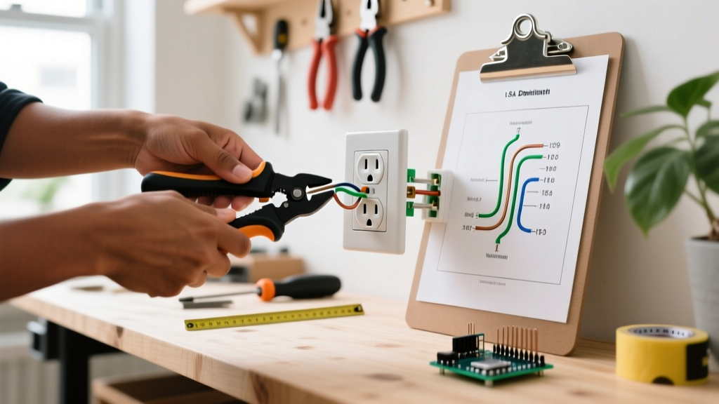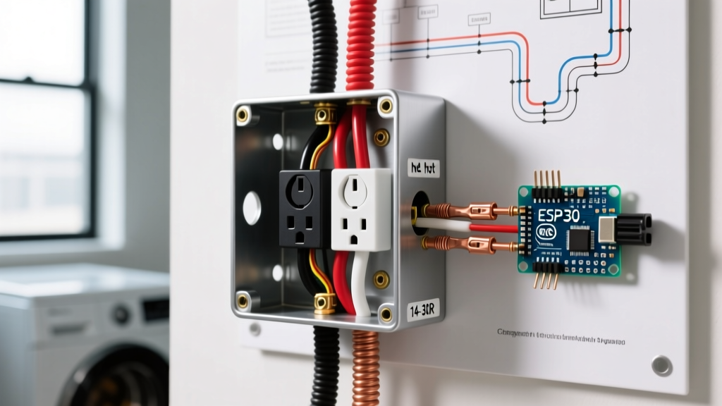

Why Upgrading Your 3-Way Switches Matters
If you are dealing with flickering hallway lights, a cracked faceplate, or a desire to integrate your home into a modern smart ecosystem, understanding the diagram for 3 way switch wiring is your critical first step. A standard 3-way switch setup allows you to control a single light fixture from two different locations, such as the top and bottom of a staircase. While the underlying physics haven't changed, the hardware and National Electrical Code (NEC) requirements have evolved significantly leading into 2026.
Upgrading from a legacy toggle switch to a premium rocker, a dimmer, or a Wi-Fi-enabled smart switch requires more than just swapping wires one-for-one. Modern smart switches often demand a neutral wire, and newer NEC guidelines enforce stricter grounding and box-fill capacities. This guide breaks down the exact wiring diagrams, upgrade paths, and edge cases you need to execute a flawless replacement.
Decoding the Standard Diagram for 3 Way Switch Wiring
Before touching a screwdriver, you must visualize the electrical flow. A standard 3-way circuit consists of four distinct wire types. Misidentifying these is the number one cause of post-installation failure.
- Line (Hot): The ungrounded conductor bringing 120V from the breaker panel to the first switch. Usually black.
- Load: The wire carrying power from the second switch to the light fixture. Usually black.
- Travelers: Two wires that run between the two 3-way switches, acting as a bridge. They swap the hot connection depending on the switch toggle position. Usually red and black, or two reds.
- Ground: The bare copper or green insulated equipment grounding conductor.
The Anatomy of the Flow
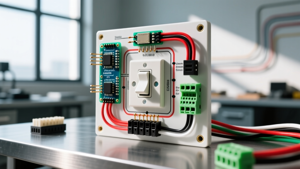
In the most common diagram for 3 way switch wiring (often called the 'Line-to-Switch-to-Switch-to-Load' configuration), power enters Switch A on the common terminal (usually a dark-colored screw). From there, it travels out via one of the two traveler terminals (brass screws) to Switch B. Switch B receives the travelers and routes the active one to its own common terminal, which then connects to the load wire heading to the ceiling fixture.
Expert Insight: Never rely on wire color alone to identify Line and Load in older homes. Previous owners may have used white wires as hot travelers without re-identifying them with black tape. Always use a non-contact voltage tester or a multimeter to verify.
Upgrade Path Matrix: Standard vs. Smart vs. Dimmer
When replacing your switches, you have three primary upgrade routes. Below is a comparison of the hardware, pricing, and wiring diagram modifications required for each in 2026.
| Upgrade Type | Recommended Model (2026) | Avg. Cost | Wiring Diagram Shift | Neutral Required? |
|---|---|---|---|---|
| Standard Rocker | Leviton Decora 5603-2W | $8.50 | 1:1 Direct Replacement. No diagram changes. | No |
| Smart Switch | Lutron Caseta PD-5WS-DV | $64.99 | Requires neutral at the switch box. Bypasses one traveler. | Yes |
| LED Dimmer | Lutron Diva DV-603P | $32.00 | Replaces one 3-way with a dimmer, the other with a standard companion. | No |
The Smart Switch Dilemma: How the Diagram Changes
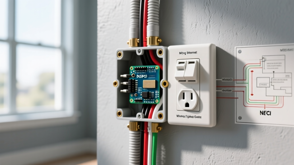
If your upgrade involves smart home integration, the traditional diagram for 3 way switch wiring gets thrown out the window. Smart switches require constant standby power to maintain their Wi-Fi, Zigbee, or Lutron Clear Connect radios. This means they must be connected to a neutral wire (the grounded conductor, usually white).
Adapting to NEC Article 404.2(C)
The NEC now mandates that a neutral wire be present at virtually all switch boxes. If your home was built after 2011, you likely have a bundle of white neutral wires capped in the back of your switch box. To upgrade to a smart switch:
- Connect the smart switch's neutral pigtail to the existing neutral bundle using a Wago 221 lever connector.
- Connect the Line and Load as dictated by the smart switch manufacturer's specific diagram.
- The Traveler Shift: Most smart 3-way setups only require one traveler wire to communicate with the companion switch or remote. You will cap off the second traveler wire in both boxes.
For deeper insights into smart home electrical safety and energy savings, refer to the U.S. Department of Energy's guide on smart switches.
Step-by-Step Replacement Workflow
Safety and precision are non-negotiable. Follow this exact workflow to ensure your upgrade passes inspection and functions flawlessly.
1. Isolate and Verify
Shut off the 15A or 20A breaker. Do not rely on the wall switch being 'off'. Use a Klein Tools NCVT-3 non-contact voltage tester on the faceplate screws, then remove the plate and test the terminal screws directly. For absolute certainty, verify zero voltage using a Fluke 117 True-RMS Multimeter between the hot terminal and the ground wire.
2. Tag the Travelers
Before disconnecting a single wire, use blue or yellow electrical tape to tag the two traveler wires. This prevents the classic 'switch only works from one location' error that occurs when travelers are accidentally swapped with the line or load.
3. Pigtailing vs. Backstabbing
Never use the push-in backstab terminals on the back of the switch. These spring-loaded contacts are notorious for arcing and failing under continuous load. Always use the side terminal screws. If you are connecting multiple ground wires, create a pigtail using a wire nut or a Wago connector, and attach a single ground wire to the switch's green grounding screw.
4. Torque to Spec
Loose connections cause resistance, heat, and fires. Use an insulated torque screwdriver set to the manufacturer's specification (typically 14 in-lbs for standard 15A/20A switch terminal screws) to ensure a secure mechanical and electrical bond.
Edge Case: The 'Dead-End' 3-Way Setup
In some older homes, you will encounter a 'dead-end' 3-way diagram. In this configuration, the power source (Line) and the Load both enter the same switch box, while the second switch box only receives the two traveler wires and a ground. It acts merely as a toggle loop.
How to Upgrade: If you are installing a standard switch, the wiring remains the same. However, if you are upgrading to a smart switch, the dead-end box will almost certainly lack a neutral wire. In this scenario, you must either pull a new 14/3 or 12/3 Romex cable to bring a neutral to the dead-end box, or pivot to a smart switch system that utilizes a wireless, battery-powered companion remote (like the Lutron Pico) instead of a hardwired second switch.
Troubleshooting Common Wiring Mistakes
If your newly installed 3-way switch isn't behaving correctly, use this diagnostic checklist before tearing it back out:
- Symptom: Light only turns on from Switch A, but not Switch B.
Diagnosis: You swapped the Line/Load wire with a Traveler wire on Switch B. The common terminal must be the exclusive source or destination, not a traveler bridge. - Symptom: The breaker trips immediately upon toggling.
Diagnosis: A ground fault or short circuit. You likely pinched a bare ground wire against a hot terminal screw when pushing the switch back into the box. Wrap the sides of the switch with electrical tape to insulate the terminals. - Symptom: Smart switch won't connect to Wi-Fi.
Diagnosis: The switch isn't getting neutral power. Verify the neutral bundle in the back of the box is actually tied to the panel's neutral bar, not just a switched loop.
Upgrading your 3-way switches is a high-impact DIY project that improves both the aesthetics and functionality of your home. By thoroughly understanding the diagram for 3 way switch wiring and respecting modern NEC safety standards, you ensure a reliable, long-lasting installation. For comprehensive electrical safety protocols and workplace standards, always consult the OSHA Electrical Safety guidelines and the NFPA 70 National Electrical Code.