
Why Screw Size and Torque Matter for Beginners
When tackling your first receptacle replacement, it is easy to become hyper-focused on matching wire colors while completely ignoring the hardware holding the connection together. However, understanding the correct screw size electrical outlet components require is not just a matter of mechanical fit; it is a critical fire safety issue. A loose terminal screw creates high electrical resistance, which generates excessive heat and can lead to arc faults or electrical fires.
As a beginner, you might assume that any small machine screw from your toolbox will work to replace a lost ground screw or secure a yoke. This is a dangerous misconception. Electrical manufacturers engineer specific thread pitches and head designs to clamp 14 AWG and 12 AWG solid copper wire with exact pressure. In this comprehensive installation tutorial, we will break down the exact hardware dimensions, teach you the proper 'shepherd's hook' wiring technique, and explain the modern torque requirements mandated by the National Electrical Code (NEC).
The Anatomy of Outlet Screws: A Hardware Matrix
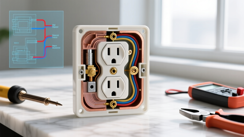
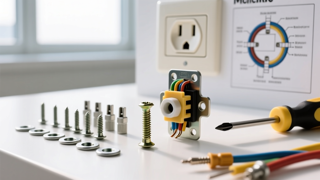
A standard 15-amp or 20-amp duplex receptacle features four distinct types of screws, each serving a unique mechanical and electrical purpose. Using the wrong thread size can strip the yoke or fail to secure the wire.
| Screw Type | Thread Size | Material / Color | Primary Function |
|---|---|---|---|
| Terminal (Hot/Neutral) | #10-32 UNC | Brass (Silver for neutral) | Clamps 14-12 AWG insulated solid copper wire to the bus bar. |
| Grounding | #10-32 UNC | Green | Secures bare copper or green ground wire to the device yoke. |
| Mounting (Yoke) | #6-32 UNC | Zinc-plated or Brass | Secures the receptacle yoke to the metal or PVC electrical box. |
| Cover Plate | #6-32 UNC | Various (matches plate) | Attaches the nylon or metal faceplate to the receptacle yoke. |
Decoding the Thread Sizes
The designation #10-32 means the screw has a nominal diameter of #10 (approximately 0.190 inches) and features 32 threads per inch (UNC stands for Unified National Coarse). This specific pitch is designed to bite into the brass terminal plate without cross-threading under high torque. The #6-32 screw is significantly thinner (approx. 0.138 inches) and is the universal standard for mounting electrical devices and cover plates in North America. If you lose a mounting screw, you can easily find a 1-inch or 1.5-inch #6-32 machine screw at any hardware store.
Step-by-Step: Wiring the #10-32 Terminal Screws
Now that you know the hardware, let us move to the workbench. Properly seating the wire under the terminal screw is where most beginners make critical errors. Follow this exact procedure for a safe, code-compliant connection.
- Strip to the Manufacturer's Gauge: Flip the receptacle over. You will see a 'strip gauge' molded into the back plastic housing. For 14 AWG wire, this is typically 3/4 inch; for 12 AWG, it is usually 7/8 inch. Use your wire strippers to remove exactly this amount of insulation. Exposing too much bare wire creates a shock hazard; exposing too little results in insulation getting trapped under the screw head.
- Form the Shepherd's Hook: Using the nose of your lineman's pliers or needle-nose pliers, grip the stripped end of the wire and bend it into a tight 'J' shape or a 270-degree hook. The radius of the bend should closely match the diameter of the #10-32 terminal screw shaft.
- Seat the Wire Clockwise: This is a non-negotiable rule in electrical work. Hook the wire around the terminal screw in a clockwise direction. As you tighten the screw with your #2 Phillips or Robertson screwdriver, the clockwise rotation will naturally pull the wire loop tighter around the shaft. If you loop it counter-clockwise, the tightening motion will push the wire out from under the screw head.
- Check for 'Insulation Bite': Look closely at the terminal. The screw head and the square washer beneath it must clamp down exclusively on bare copper. If the plastic wire insulation is caught under the washer, the connection will eventually loosen as the plastic compresses and degrades over time.
- Tighten to Torque Spec: Snug the screw down firmly until the wire cannot move. (We will cover exact torque measurements in the next section).
Pro-Tip for Deep Boxes: If you are working in a deep junction box where the receptacle sits far back, do not over-tighten the terminal screws to 'pull' the device forward. This bends the yoke and stresses the internal bus bar. Instead, use longer #6-32 mounting screws or add a plastic box extender ring to bring the mounting surface flush with the drywall.
Mounting the Receptacle: Dealing with #6-32 Yoke Screws
Once your wires are terminated, it is time to secure the device to the electrical box. Standard receptacles come with 1-inch long #6-32 mounting screws. However, modern installations often involve thick drywall, tile, or wood paneling.
If the receptacle ears do not sit flush against the wall surface, you will need to purchase longer #6-32 screws (commonly 1.5-inch or 2-inch lengths) and use plastic shims (often called 'caterpillars' or 'shim-it' strips) behind the mounting ears. This prevents the cover plate from cracking when you tighten the #6-32 cover plate screws, and it ensures the outlet does not push inward when you plug in a stiff appliance cord.
Critical Code Compliance: Torque Specifications
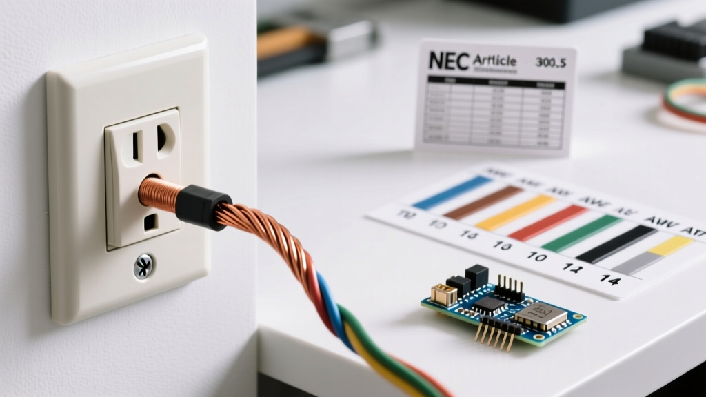
One of the most significant shifts in modern electrical safety is the strict enforcement of terminal torque. According to the National Fire Protection Association (NFPA) and NEC Section 110.14(D), equipment terminals must be tightened to the torque values specified by the manufacturer using a calibrated torque tool. This rule, which began heavy enforcement in 2017, is standard practice in 2026.
For standard 15A and 20A residential duplex receptacles (from brands like Leviton, Hubbell, or Eaton), the manufacturer typically specifies a torque range of 12 to 14 inch-pounds for the #10-32 terminal screws.
As a beginner, you might wonder how to achieve this without a professional tool. While a dedicated torque screwdriver (such as the Klein Tools 60005 or CDI 401SM, which retail between $45 and $65) is highly recommended for your toolkit, the absolute minimum requirement for a DIYer is to tighten the screw until the wire is completely immobilized and the square lock-washer is fully flattened, without applying enough force to strip the brass head. For authoritative guidance on residential electrical safety practices, always consult resources provided by the Electrical Safety Foundation International (ESFI).
3 Fatal Beginner Mistakes to Avoid
Even if you know the correct screw size for an electrical outlet, poor execution can ruin the installation. Watch out for these common pitfalls:
1. The 'Backstab' Push-In Connection
Many modern receptacles feature quick-wire push-in holes on the back. While these accept 14 AWG wire without using the terminal screws, they rely on internal spring-loaded wedges rather than the mechanical clamping force of a #10-32 screw. Industry professionals overwhelmingly prefer the side-wire screw terminals for their superior long-term reliability and lower resistance. Use the screws; avoid the backstabs.
2. Over-Tightening and Stripping
Brass is a relatively soft metal. If you use a power drill with a high clutch setting to drive the #10-32 terminal screws, you risk stripping the screw head or snapping the shaft entirely. If a terminal screw snaps off inside the brass bus bar, the receptacle is ruined and must be thrown away. Always use a hand screwdriver for final tightening.
3. Mixing Up Ground and Neutral
Both the neutral wire (white) and the ground wire (bare/green) connect to screws that are bonded together in a standard circuit, but they must go to their designated locations. The neutral wire connects to the silver #10-32 terminal screws. The ground wire connects exclusively to the green #10-32 grounding screw at the bottom of the yoke. Reversing these or placing the neutral on the ground screw can cause GFCI breakers to trip immediately and creates a dangerous parallel neutral path.
Final Thoughts on Hardware and Safety
Mastering the basics of receptacle wiring means respecting the small details. The #10-32 terminal screw and the #6-32 mounting screw are not just generic fasteners; they are precisely engineered components designed to maintain a secure, low-resistance electrical path for decades. By stripping your wires to the exact gauge, forming proper clockwise loops, and tightening to the manufacturer's torque specifications, you ensure your DIY installation is as safe and reliable as one performed by a master electrician. Always turn off the power at the main breaker panel and verify with a non-contact voltage tester before beginning any electrical work.