
Why Electrical Outlet Screws Dictate System Safety
When wiring a standard 15-amp or 20-amp receptacle, the physical connection point between the copper conductor and the brass terminal is the most vulnerable node in your electrical system. While modern wire nuts and push-in connectors have their place, electrical outlet screws remain the gold standard for low-resistance, high-reliability terminations. However, simply tightening a screw until it feels secure is no longer compliant with modern electrical codes, nor is it safe.
As of the 2026 enforcement cycles, inspectors are strictly applying torque mandates and thread specifications to prevent thermal expansion failures, arc faults, and localized fires. This guide breaks down the exact National Electrical Code (NEC) requirements governing electrical outlet screws, from terminal torque values to the critical differences between #6-32 and #10-32 threading.
The NEC Mandate: Torque Requirements for Outlet Terminals
Historically, electricians relied on the "two-finger tight" or "wrist-flick" method to secure wires. This changed dramatically with the introduction and subsequent strict enforcement of NEC 110.14(D), which mandates that all terminations must be tightened to the manufacturer's specified torque using a calibrated torque tool.
According to the National Fire Protection Association (NFPA), failure to use a calibrated torque screwdriver on listed equipment is a direct code violation. Under-torquing leads to micro-movements during thermal cycling (when the wire heats up under load and cools down), eventually causing the wire to loosen, arc, and ignite surrounding materials.
Standard Torque Values for 15A and 20A Receptacles
Most commercial and residential duplex receptacles (such as the Leviton 5262 or Hubbell HBL5262) require specific inch-pound (in-lb) torque settings based on the wire gauge and the grade of the device. Below are the standard manufacturer specifications for side-wired terminal screws:
| Receptacle Grade | Wire Gauge (AWG) | Required Torque (in-lbs) | Tool Recommendation |
|---|---|---|---|
| Residential (e.g., Leviton T5262) | 14 AWG Solid | 12 in-lbs | Klein Tools 69070 |
| Residential (e.g., Leviton T5262) | 12 AWG Solid | 12 in-lbs | Klein Tools 69070 |
| Commercial / Hospital Grade | 14 - 10 AWG | 14 in-lbs | Wiha 28502 TorqueVario |
Expert Warning: Never use a standard VDE-insulated screwdriver to achieve final torque. Over-torquing a brass terminal screw on a residential-grade nylon yoke can strip the threads or crack the internal clamp plate, creating a hidden high-resistance fault that will fail under a continuous 16-amp load.
Thread Standards: #6-32 vs. #10-32 Compliance
A common and dangerous mistake made by DIYers and apprentice electricians is confusing the threading used for device mounting versus box grounding. The NEC is highly specific about the metallurgy and threading of screws used in outlet boxes.
Device Mounting and Terminal Screws (#6-32 UNC)
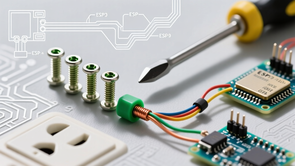
The screws that secure the receptacle yoke to the electrical box, as well as the brass and green terminal screws on the device itself, are almost universally #6-32 UNC (Unified National Coarse) machine screws. Per NEC 406.5, receptacles must be secured to the box using machine screws that match the threading of the mounting holes. Using drywall screws or wood screws to mount an outlet to a metal box is a severe violation that compromises the grounding path and mechanical stability.
Metal Box Grounding Screws (#10-32 UNC)
When attaching a grounding pigtail directly to a metal electrical box, NEC 250.148(C) explicitly requires a #10-32 UNC screw. The #6-32 screws used for electrical outlet screws and device mounting are physically too small to provide the requisite surface area and thread engagement for a fault-current path. Using a #6-32 terminal screw to ground a wire to a metal box will result in an immediate inspection failure and a dangerous bottleneck during a short-circuit event.
Terminal Connection Methods: Side-Wire vs. Back-Wire
Understanding how electrical outlet screws interact with different wiring methods is crucial for passing inspection and ensuring longevity.
- Side-Wiring (Loop Method): The wire is stripped, looped clockwise around the brass terminal screw, and tightened. The screw head and the terminal plate clamp the wire. This method requires precise loop sizing; if the loop is too large, it will slip out from under the screw head when torqued.
- Back-Wiring (Clamp-Plate Method): Found on commercial and spec-grade receptacles, the wire is inserted straight into a rear hole. Tightening the terminal screw draws up a heavy-duty copper alloy clamp plate that secures the wire. This is the most secure method, as the screw's torque is applied to a flat plate rather than directly crushing the copper wire.
- Push-In (Back-Stabbing): While not utilizing a screw for the connection itself, it is vital to note that NEC inspectors and industry professionals heavily discourage push-in connections for 12 AWG wire due to historical failure rates. Always use the terminal screws or back-wire clamp plates.
Grounding Screw Rules: The Green Terminal
NEC 250.148 and 406.4 dictate strict identification rules for grounding connections. The grounding screw on a standard receptacle is always colored green or marked with a green hexagonal head. This screw connects to the receptacle's internal grounding bus and the metal yoke.
Pigtailing Requirement: When wiring multiple outlets in a daisy-chain (series) configuration, the equipment grounding conductor (EGC) must be continuous or properly pigtailed. You cannot rely solely on the green grounding screw and the metal yoke to pass ground continuity to the next downstream device if the hot and neutral are also daisy-chained on the terminal screws. The NEC requires the grounding path to remain intact even if a single receptacle is removed for replacement.
Troubleshooting Common Screw-Related Failure Modes
Even with proper tools, electrical outlet screws can fail if environmental or mechanical factors are ignored. Below is a diagnostic matrix for common field failures:
| Failure Symptom | Root Cause | Corrective Action |
|---|---|---|
| Screw head strips during installation | Using a worn #2 Phillips bit or incorrect torque driver setting. | Discard the receptacle. Never use a stripped terminal screw, as it cannot maintain clamp pressure under thermal load. |
| Discoloration / melting around brass screw | Under-torqued wire causing micro-arcing, or aluminum wire used without CO/ALR rating. | Cut back damaged wire, strip fresh insulation, and torque to 14 in-lbs on a new commercial-grade receptacle. |
| Screw snaps off inside the yoke | Over-torquing past 18 in-lbs or cross-threading during factory assembly. | Device is unrepairable. Replace the receptacle. Verify torque tool calibration. |
| Wire pulls out under gentle tug | Wire stripped too short (less than 3/4") or looped counter-clockwise. | Strip wire to exactly 3/4 inch, loop clockwise so screw rotation tightens the loop. |
Step-by-Step: Properly Torquing Electrical Outlet Screws
Follow this procedure to ensure every receptacle you install in 2026 meets NEC 110.14(D) standards:
- Strip the Wire: Use a precision wire stripper (like the Klein 11055) to remove exactly 3/4 inch of insulation from 12 AWG or 14 AWG solid copper wire.
- Form the Loop: Using needle-nose pliers, form a tight, clockwise loop. The loop should match the diameter of the screw shaft, not the screw head.
- Seat the Wire: Place the loop around the terminal screw. Ensure the insulation jacket butts up against the terminal plate, but no bare copper is exposed outside the plate (NEC 110.14(A) requires no exposed copper that could cause a short).
- Set the Torque Driver: Adjust your calibrated torque screwdriver (e.g., Klein Tools Torque Screwdriver) to the manufacturer's spec (typically 12 or 14 in-lbs).
- Tighten to Click:Drive the screw until the torque driver slips or clicks. Do not re-tighten after the click, as this can over-stress the brass threads.
- The Pull Test: Give the wire a firm, sharp tug to ensure it is fully seated and clamped.
Frequently Asked Questions (FAQ)
Can I use drywall screws to mount an outlet to a wooden stud?
No. While the receptacle mounts to the electrical box (not the stud), the screws securing the device to the box must be #6-32 machine screws. If you are mounting a plastic "old work" box to drywall, the box's built-in flanges are used, but the device itself still requires #6-32 machine screws.
What if the brass terminal screw on my receptacle is stripped?
A stripped terminal screw compromises the clamp pressure, leading to high resistance and heat. You cannot simply replace the screw with a hardware store machine screw, as the metallurgy and head profile are specific to the UL-listed design of the receptacle. You must replace the entire receptacle.
Are back-wired clamp plates better than side-wired screws?
Yes. For commercial applications and high-load residential circuits (like kitchen countertops or EV charger outlets), back-wired receptacles utilize the terminal screw to pull a heavy clamp plate flat against the wire. This provides superior surface contact, eliminates the risk of the wire slipping out from under a screw head, and makes torquing significantly more consistent.
Final Thoughts on Code Compliance
The era of guessing torque values is over. As electrical loads in modern homes increase due to smart home hubs, high-wattage appliances, and continuous-duty electronics, the physical integrity of your terminations is paramount. Investing in a calibrated torque screwdriver and adhering strictly to the manufacturer's specifications for electrical outlet screws is not just about passing inspection—it is the fundamental baseline for preventing electrical fires and ensuring a safe, reliable power distribution system.