
Decoding the Electrical Wiring Diagram for Outlet Compliance
Drafting or interpreting an electrical wiring diagram for outlet installations is only the first step in a successful project. The true test of any wiring schematic is its adherence to the National Electrical Code (NEC). As of the 2026 inspection cycles, local authorities having jurisdiction (AHJs) are strictly enforcing updated mandates regarding receptacle spacing, arc-fault protection, and precise termination torque values. A diagram that looks functional on paper can easily fail inspection—or worse, cause a fire—if it ignores these critical code requirements.
Whether you are wiring a new addition, upgrading a kitchen, or replacing outdated two-prong receptacles, your electrical wiring diagram for outlet layouts must reflect current safety standards. According to the National Fire Protection Association (NFPA), electrical malfunctions remain a leading cause of residential fires. This guide breaks down the exact NEC articles you must integrate into your outlet wiring plans to ensure safety, functionality, and code compliance.
Core NEC Spacing Rules: Article 210.52
When reviewing an electrical wiring diagram for outlet layouts, the most frequently cited violation involves improper spacing. NEC Article 210.52 dictates exactly where receptacles must be placed to prevent the use of extension cords, which the U.S. Consumer Product Safety Commission (CPSC) identifies as a major fire and shock hazard.
The 6-Foot / 12-Foot Rule
For general living areas (living rooms, bedrooms, hallways), the NEC mandates that no point along a continuous wall space can be more than 6 feet from a receptacle. Consequently, receptacles must be spaced no more than 12 feet apart. Your diagram must account for wall breaks, doorways, and fireplaces that interrupt the continuous wall measurement.
Countertop and Kitchen Mandates
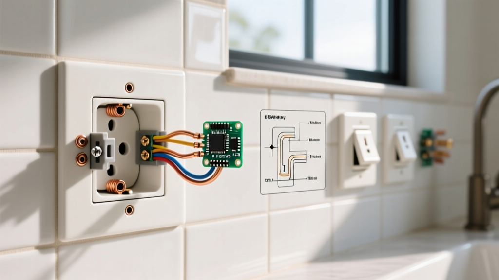
Kitchen diagrams require much tighter spacing. NEC 210.52(C) requires that no point along a countertop wall line can be more than 24 inches from a receptacle. Furthermore, any countertop island or peninsular space measuring at least 12 inches by 24 inches requires a minimum of one receptacle, with additional outlets required for every additional 8 square feet of surface area.
| Area Type | NEC Article | Maximum Distance Between Outlets | Maximum Distance from Wall Edge |
|---|---|---|---|
| General Living Spaces | 210.52(A) | 12 feet | 6 feet |
| Kitchen Countertops | 210.52(C)(1) | 48 inches | 24 inches |
| Islands / Peninsulas | 210.52(C)(2) | 1 per 8 sq. ft. | N/A (Specific placement rules apply) |
| Bathrooms | 210.52(D) | N/A | 36 inches from basin edge |
GFCI and AFCI Mandates: Articles 210.8 & 210.12
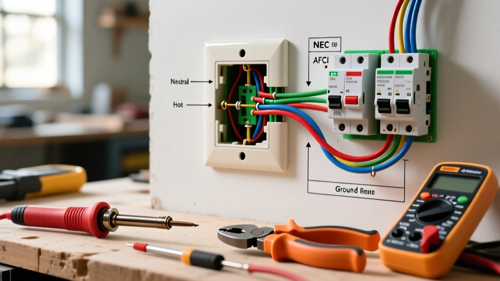
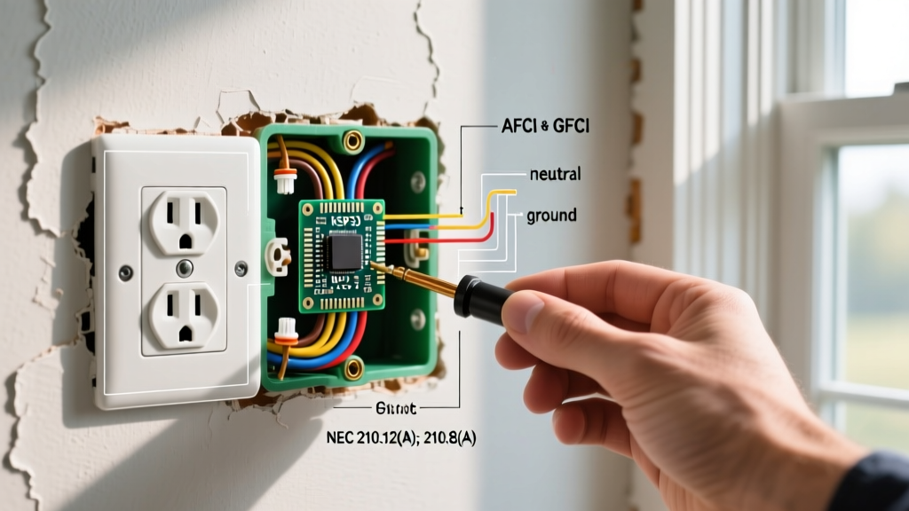
A modern electrical wiring diagram for outlet circuits must explicitly note where Ground Fault Circuit Interrupter (GFCI) and Arc Fault Circuit Interrupter (AFCI) protection is required. Relying solely on standard 15A or 20A breakers is a guaranteed code violation in most rooms.
Where GFCI Protection is Mandatory (Article 210.8)
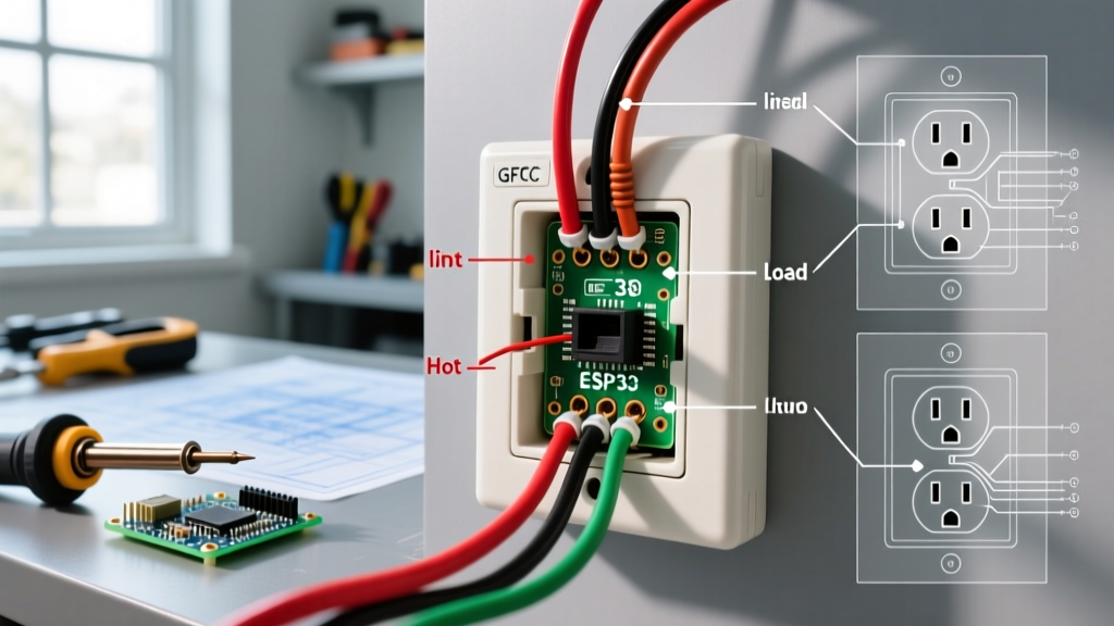
GFCI protection is required in all areas where water and electricity intersect. Your diagram must specify GFCI receptacles or GFCI breakers for:
- Kitchens (all countertop receptacles)
- Bathrooms
- Garages and accessory buildings with dirt or concrete floors
- Outdoor receptacles (including those under eaves)
- Crawl spaces and unfinished basements
- Laundry areas and utility sinks
Where AFCI Protection is Mandatory (Article 210.12)
AFCI protection prevents electrical fires caused by arcing faults in damaged or deteriorating wire. In current code cycles, AFCI protection is required for nearly all 120V, 15A, and 20A branch circuits supplying living spaces, including bedrooms, living rooms, closets, and hallways.
Pro Tip: For areas requiring both protections (like a kitchen or laundry room), update your diagram to specify Dual-Function (DF) receptacles, such as the Leviton AFGFI1-W. This eliminates the need for a specialized combination AFCI/GFCI breaker in the main panel, saving roughly $35 to $50 per circuit in material costs.
Wire Gauge and Breaker Sizing Matrix
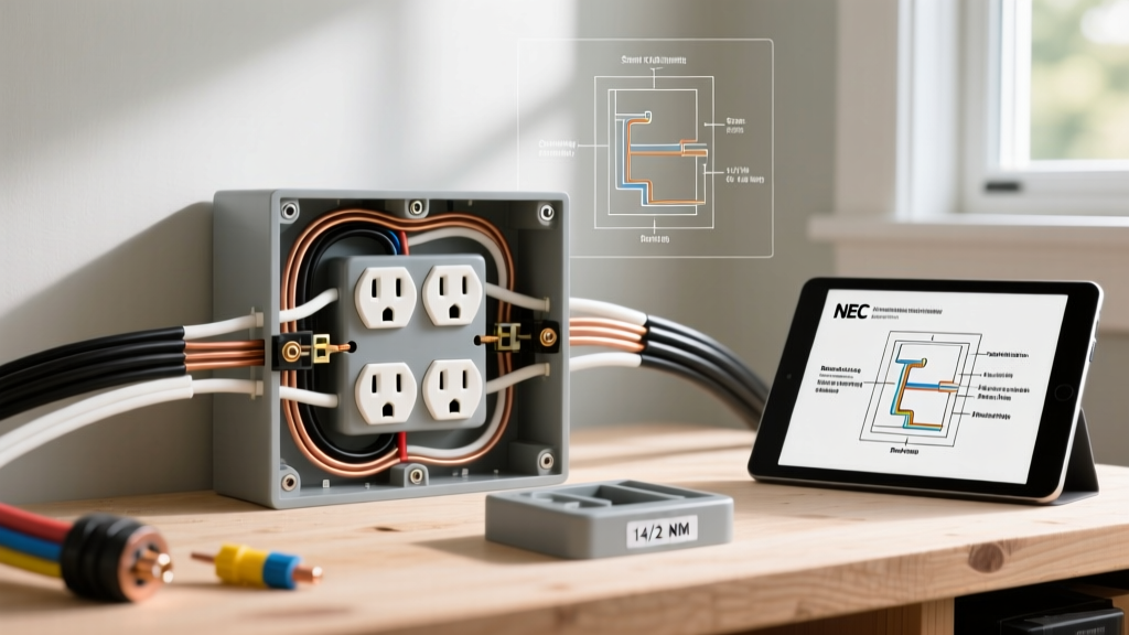
An accurate electrical wiring diagram for outlet installations must clearly label the wire gauge (AWG) and the corresponding overcurrent protection device (breaker) size. Mixing these up is a severe violation of NEC Article 240.4.
| Breaker Size | Minimum Copper Wire Gauge (THHN/THWN) | Standard Receptacle Type | Common Application |
|---|---|---|---|
| 15 Amp | 14 AWG | NEMA 5-15R (Standard 3-prong) | Bedrooms, Living Rooms, Lighting |
| 20 Amp | 12 AWG | NEMA 5-15R or NEMA 5-20R (T-slot) | Kitchens, Bathrooms, Garages, Laundry |
| 30 Amp | 10 AWG | NEMA L14-30R (Twist-lock) | Dryers, RV Hookups, Heavy Machinery |
Continuous Load Rule: If your diagram includes outlets dedicated to continuous loads (devices expected to run for 3 hours or more, like a countertop warming drawer or a dedicated window AC unit), NEC Article 210.20(A) requires the breaker to be rated at 125% of the continuous load. A 12A continuous load requires a 15A breaker minimum, but upgrading to 12 AWG wire on a 20A breaker provides a safer thermal margin.
Termination Torque: The Hidden Code Requirement
One of the most overlooked aspects of outlet wiring is termination torque. Since the 2017 NEC update, and heavily enforced in 2026 inspections, NEC Article 110.14(D) requires that all electrical connections be tightened to the manufacturer's specified torque using a calibrated torque screwdriver.
Most standard 15A and 20A duplex receptacles (such as those from Hubbell or Leviton) require a termination torque between 12 and 16 inch-pounds. Hand-tightening with a standard screwdriver often results in under-torqued connections, which loosen over time due to thermal expansion and contraction, leading to high-resistance arcing and fires. Your diagram's installation notes should explicitly state: 'All terminations must be torqued to manufacturer specifications per NEC 110.14(D).'
Back-Wiring vs. Side-Wiring
While push-in (back-stab) connections are technically code-legal for 14 AWG solid wire on 15A circuits, they rely on a small internal spring clip that is prone to failure over time. Best practice for your diagram is to specify side-wiring (looping the wire around the terminal screw) or utilizing spec-grade receptacles with internal back-wire clamps (which securely clamp the wire under a metal plate when the screw is tightened).
Multi-Wire Branch Circuits (MWBC) and Handle Ties
If your electrical wiring diagram for outlet layouts utilizes a Multi-Wire Branch Circuit (sharing a single neutral wire between two hot legs to save copper), you must comply with NEC Article 210.4.
The code strictly requires that all ungrounded (hot) conductors of an MWBC be provided with a means to disconnect simultaneously. In your panel schedule and wiring diagram, you must specify a 2-pole breaker or two single-pole breakers equipped with an approved handle tie (e.g., Eaton CHMT1 or Square D HOMHT). Failing to include a handle tie means an electrician could turn off one breaker to work on an outlet, unaware that the shared neutral is still carrying the return current from the adjacent live circuit, presenting a lethal shock hazard.
Summary Checklist for Your Diagram
Before submitting your electrical wiring diagram for outlet permitting, verify the following:
- Spacing: Does the layout meet the 6ft/12ft general rule and 24-inch countertop rule?
- Protection: Are GFCI and AFCI zones clearly marked according to Articles 210.8 and 210.12?
- Sizing: Are 20A kitchen/bathroom circuits paired with 12 AWG wire?
- Termination: Is the torque requirement noted for the installer?
- MWBC Safety: Are shared neutrals protected by 2-pole breakers or handle ties?
By integrating these specific NEC requirements directly into your electrical wiring diagram for outlet projects, you ensure a safer installation, pass inspections on the first attempt, and protect the end-users from the leading causes of residential electrical fires.