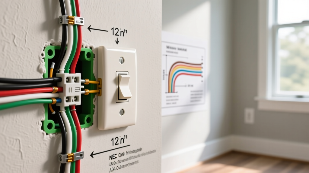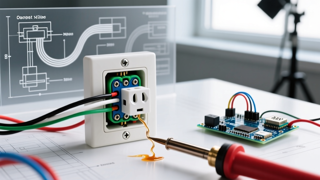

Beyond the Breaker: Code-Compliant Receptacle Diagnostics
When a receptacle fails, most DIYers immediately head to the breaker panel, flip a switch, and assume the problem is solved if power returns. However, professional electricians know that a tripped breaker or a dead outlet is merely a symptom of a deeper underlying issue. Performing proper electrical outlet troubleshooting steps requires more than just a cheap three-light tester; it demands a systematic approach grounded in the National Electrical Code (NEC). Ignoring code requirements during diagnostics can lead to undetected shock hazards, arc faults, and catastrophic electrical fires.
In this guide, we break down advanced diagnostic procedures, mapping common receptacle failures directly to NEC violations and detailing the exact corrective actions required to bring your electrical system up to modern safety standards.
Phase 1: Safety Protocols and Baseline Verification
Before removing a single faceplate, you must establish a safe testing environment. According to OSHA electrical safety guidelines, working on energized circuits without proper PPE and testing equipment is a primary cause of residential electrical injuries.
Required Diagnostic Tools
- True-RMS Multimeter: A professional-grade meter like the Fluke 117 (approx. $200) is essential for detecting phantom voltages and measuring exact voltage drops.
- Non-Contact Voltage Tester (NCVT): The Klein Tools NCVT-3 (approx. $35) features dual-range detection (12V to 1000V) to verify the absence of voltage before touching bare conductors.
- Receptacle Tester: A Gardner Bender GRT-925 (approx. $15) is useful for initial triage, but as we will discuss later, it can be easily fooled by illegal wiring modifications.
Phase 2: Diagnostic Matrix for Common Receptacle Failures
Use the following matrix to correlate your multimeter readings with specific NEC code violations. This framework ensures your electrical outlet troubleshooting steps yield actionable, code-compliant solutions.
| Symptom / Reading | Probable Root Cause | NEC Code Violation Risk | Corrective Action |
|---|---|---|---|
| Hot-Neutral: 120V Hot-Ground: 0V |
Open Equipment Grounding Conductor (EGC) | NEC 250.148 (Failure to bond grounding conductor) | Trace EGC back to panel; repair broken bare copper or install GFCI per 406.4(D)(2). |
| Hot-Neutral: 120V Neutral-Ground: 120V |
Reversed Polarity or Open Neutral | NEC 200.11 (Polarity of connections) | Verify white wire is on silver terminal, black on brass. Check for broken neutral splice. |
| Breaker trips immediately upon plugging in a load | Dead short or ground fault downstream | NEC 240.4 (Overcurrent protection) | Isolate downstream loads; check for pierced wire insulation or crushed cables. |
| GFCI trips with no load attached | Shared neutral or Line/Load miswiring | NEC 210.8 (GFCI protection requirements) | Ensure downstream neutrals are not mixing; verify LINE vs LOAD terminals. |
Phase 3: The 'Bootleg Ground' Deception
One of the most critical electrical outlet troubleshooting steps involves identifying a 'bootleg ground.' This occurs when a previous homeowner or unlicensed handyman connects a jumper wire between the neutral (silver) terminal and the ground (green) terminal on a two-prong ungrounded circuit to trick a home inspector's three-light receptacle tester.
NEC 250.148 Warning: The equipment grounding conductor must never be used as a neutral return path. A bootleg ground places 120V on the metal chassis of any plugged-in appliance if the neutral wire fails, creating a lethal shock hazard.
How to Expose a Bootleg Ground with a Multimeter
- Measure Hot to Neutral: Expect ~120V. If the receptacle is wired correctly, you have a baseline.
- Measure Hot to Ground: Expect ~120V. If this reads 0V, you have an open ground. If it reads 120V, proceed to step 3.
- Measure Neutral to Ground: This is the tell-tale test. A properly grounded circuit will show a voltage drop of less than 0.5V between neutral and ground. If your multimeter reads exactly 0.00V, you likely have a bootleg ground (a direct physical jumper) rather than a true ground path back to the panel.
- The Load Test: Plug in a high-draw device (like a hairdryer). If the Neutral-to-Ground voltage spikes significantly, or if you measure voltage on the metal faceplate screw, shut off the breaker immediately and remove the receptacle to verify the physical wiring.
Phase 4: Code Upgrades Required During Troubleshooting
When your electrical outlet troubleshooting steps reveal a failed or damaged receptacle, the NEC requires that the replacement meet current safety standards, not the standards of the year the home was built. As local jurisdictions adopt the 2023 NEC (with widespread enforcement continuing into 2026), two major upgrades are mandatory during replacements.
1. Tamper-Resistant (TR) Receptacles
Under NEC 406.12, all 15- and 20-ampere, 125- and 250-volt nonlocking receptacles in residential dwelling units must be listed as Tamper-Resistant. If you are troubleshooting a dead outlet in a living room and find the internal contacts are burned out, you cannot replace it with a standard $0.60 receptacle. You must install a TR receptacle (e.g., Leviton T5325, approx. $2.50), which features internal shutters that prevent children from inserting foreign objects.
2. Torque Requirements for Terminals
Loose connections cause arcing, which leads to melted faceplates and electrical fires. NEC 110.14(D) mandates that electrical connections must be tightened to the manufacturer's specified torque using a calibrated tool. Most modern Leviton and Eaton commercial-grade receptacles specify a torque value of 14 in-lbs for 14 AWG and 12 AWG solid copper wire. Using a calibrated torque screwdriver (like the Klein Tools 60514) is no longer just a best practice; it is a strict code requirement.
Phase 5: GFCI and AFCI Integration Troubleshooting
Modern troubleshooting frequently involves dual-function AFCI/GFCI receptacles or breakers. The NFPA National Electrical Code has vastly expanded the areas requiring Ground Fault Circuit Interrupter (GFCI) protection, including kitchens, bathrooms, garages, outdoors, crawl spaces, and unfinished basements.
If a GFCI receptacle refuses to reset during your troubleshooting:
- Check for Load-Side Neutral Mixing: If a downstream standard receptacle shares a neutral with a different circuit, the GFCI will detect the current imbalance and trip immediately. Neutrals must never be shared downstream of a GFCI.
- Verify Line vs. Load: A common installation error is connecting the incoming power to the LOAD terminals and the downstream wires to the LINE terminals. While the GFCI might power up, it will fail to protect downstream devices and may exhibit erratic tripping behavior.
- Moisture Ingress: For outdoor receptacles, ensure the in-use weatherproof cover is intact. The CPSC Electrical Safety guidelines frequently cite moisture intrusion in degraded outdoor enclosures as a primary cause of nuisance GFCI tripping.
Frequently Asked Questions (FAQ)
Can I just install a GFCI to fix an ungrounded outlet?
Yes, under NEC 406.4(D)(2)(c), if no equipment grounding conductor exists in the branch circuit, you may install a GFCI receptacle to provide shock protection. However, the faceplate must be labeled with the included 'No Equipment Ground' and 'GFCI Protected' stickers. This does not provide a true ground for surge protectors, but it satisfies the code for shock mitigation.
Why does my receptacle tester show 'Open Neutral' but the multimeter shows 120V?
Standard three-light testers require a minimum current draw to illuminate the neon bulbs. If you have a high-resistance connection (a 'floating' neutral caused by a loose backstabbed wire), a high-impedance digital multimeter might read 120V (phantom voltage), but the tester will fail to light the neutral indicator. Always trust a True-RMS multimeter over a three-light tester for definitive diagnostics.
Are backstabbed push-in connections a code violation?
While not explicitly banned by the NEC, push-in (backstab) connections are limited to 14 AWG solid copper wire under UL listing requirements. They are notorious for failing under thermal expansion and contraction cycles. For reliable, code-compliant troubleshooting and repair, always migrate backstabbed wires to the side-screw terminals or use properly torqued pigtails.