
Understanding the Circuit Topology
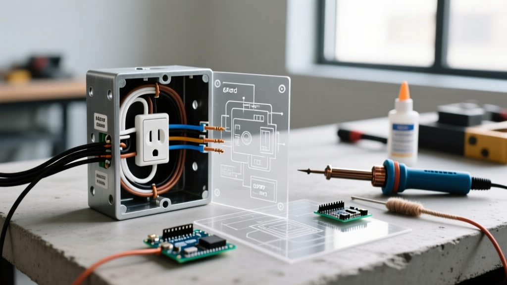
When expanding a residential branch circuit, electricians frequently encounter the need to insert a new receptacle between two existing points. Adding an electrical outlet in the middle of a run means interrupting an existing continuous cable to splice in a new junction box and receptacle. Unlike adding an outlet at the 'end of a run' (where only one cable enters the box), a middle-of-run installation requires managing two cables: the 'Line In' (power arriving from the panel or upstream device) and the 'Load Out' (power continuing to downstream devices).
Mishandling this topology is a leading cause of downstream power loss, high-resistance connections, and electrical fires. According to the U.S. Consumer Product Safety Commission (CPSC), faulty receptacle connections contribute to thousands of residential fires annually. This wiring diagram reference provides the exact technical specifications, NEC-compliant methodologies, and terminal matrices required to execute this modification safely.
Wiring Diagram Reference: Terminal Connection Matrix
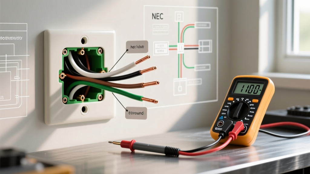
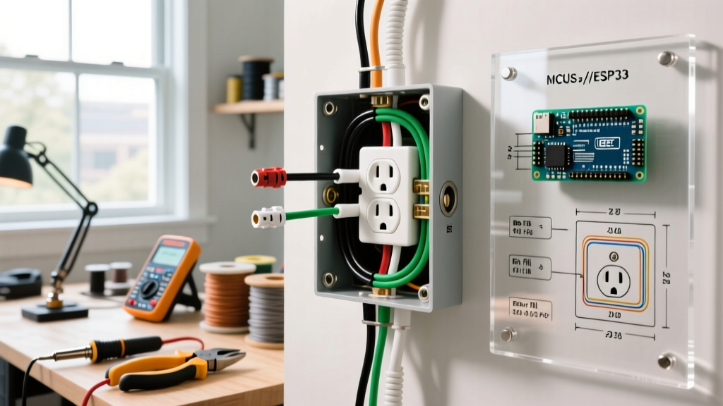
Unlike end-of-run configurations, a middle-of-run box houses two separate Romex (NM-B) cables. You must combine the incoming and outgoing conductors of the same color before routing them to the receptacle. Below is the definitive connection matrix for a standard 15-amp or 20-amp, 120-volt split-wire receptacle.
| Cable Source | Wire Color | Function | Connection Point |
|---|---|---|---|
| Line In (Upstream) | Black | Ungrounded (Hot) | Pigtail to Brass Screw (Top or Bottom) |
| Load Out (Downstream) | Black | Ungrounded (Hot) | Pigtail to Brass Screw (Same as Line In) |
| Line In (Upstream) | White | Grounded (Neutral) | Pigtail to Silver Screw |
| Load Out (Downstream) | White | Grounded (Neutral) | Pigtail to Silver Screw (Same as Line In) |
| Line In & Load Out | Bare / Green | Equipment Ground | Pigtail to Green Grounding Screw & Metal Box |
Pigtailing vs. Pass-Through: The NEC Perspective
A critical decision when adding an electrical outlet in the middle of a run is whether to 'daisy-chain' (pass-through) the wires directly through the receptacle's push-in backstabs or screw terminals, or to use 'pigtails'. While the National Electrical Code (NEC) technically permits using the receptacle's terminal screws to splice the line and load wires together, industry best practices and National Fire Protection Association (NFPA) guidelines strongly advocate for pigtailing.
Why Pigtailing is Mandatory for Professional Work
- Continuity Independence: If you pass the neutral wires through the receptacle's silver screws and the receptacle fails or is removed for painting, the downstream outlets lose their neutral return path. This can create a dangerous series circuit (shared neutral) across downstream 120V loads, potentially sending 240V to 120V appliances.
- Box Fill & Heat Dissipation: Push-in backstab connections are notorious for high-resistance failures under continuous load. Pigtailing using Wago 221-413 lever nuts or Ideal 341 wire nuts keeps the bulk of the splicing away from the receptacle yoke, reducing localized heat.
- NEC 110.14 Torque Requirements: Standard receptacle screws are not rated to securely clamp two 12 AWG solid wires simultaneously without risk of the wires slipping or the screw stripping.
Expert Tip: Abandon traditional twist-on wire nuts for middle-of-run splices in tight boxes. Use Wago 221 series lever nuts. They require less wire stripping length, eliminate the torque-twisting that can snap 14 AWG solid copper, and allow for instant continuity testing via the built-in test ports.
NEC Box Fill Calculations (Article 314.16)
The most common code violation when adding an outlet in the middle of a run is box overcrowding. Because you are introducing two cables instead of one, the conductor count doubles. Per NEC Article 314.16, you must calculate the minimum cubic inch (cu in) volume required for the electrical box.
Volume Allowance Multipliers
Each conductor, device, and clamp requires a specific volume allowance based on wire gauge:
- 14 AWG Wire: 2.0 cu in per allowance
- 12 AWG Wire: 2.25 cu in per allowance
Calculation Example: 14 AWG Middle-of-Run Box
- Hot Wires: 2 entering, 1 pigtail = 3 allowances (6.0 cu in)
- Neutral Wires: 2 entering, 1 pigtail = 3 allowances (6.0 cu in)
- Ground Wires: All grounds combined count as 1 allowance (2.0 cu in)
- Device (Receptacle): Counts as 2 allowances based on largest wire (4.0 cu in)
- Internal Clamps: Count as 1 allowance (2.0 cu in)
- Total Minimum Volume Required: 20.0 cubic inches.
Note: A standard 'single-gang' old-work box is typically 14 to 18 cu in. For a middle-of-run addition, you must purchase a 'deep' single-gang box (minimum 20-22 cu in) or upgrade to a double-gang box to remain NEC compliant.
Step-by-Step Installation Protocol
Follow this precise workflow to ensure a safe, code-compliant installation.
Step 1: Verification and Cable Preparation
Shut off the breaker and verify zero voltage using a non-contact voltage tester (e.g., Klein Tools NCVT-3). Cut the existing NM-B cable cleanly. Strip the outer jacket back exactly 8 inches from the entry point of the box to comply with NEC 300.14, which mandates at least 6 inches of free conductor length measured from the front edge of the box.
Step 2: Creating the Pigtails
Cut three 6-inch pigtail wires matching the circuit gauge (14 AWG for 15A, 12 AWG for 20A).
- Strip 3/4 inch of insulation from one end of each pigtail.
- Strip 1/2 inch from the Line In and Load Out black wires, and combine them with the black pigtail using a lever nut.
- Repeat for the white neutral wires.
- For the bare copper grounds, use a crimp ring or pigtail to a green grounding pigtail, ensuring the metal box (if applicable) is also bonded.
Step 3: Termination and Torque
Form a clockwise shepherd's hook on the exposed ends of your pigtails. Hook the black pigtail onto the top brass terminal and the white pigtail onto the top silver terminal. Tighten the terminal screws. While residential electricians often tighten by feel, the UL standard for standard 15A/20A receptacles specifies a torque of roughly 12 to 14 inch-pounds. Use a calibrated torque screwdriver if available to prevent stripping the brass threads.
Step 4: Box Dressing and Securing
Neatly fold the wires into the back of the deep box. Push the ground wires in first, followed by the neutrals, and finally the hots. This 'ground-first' layering prevents the bare copper from accidentally resting against the hot brass screws. Secure the Leviton or Eaton tamper-resistant (TR) receptacle to the box, ensuring the yoke sits flush against the drywall to prevent the faceplate from cracking.
Troubleshooting Edge Cases
Even with a perfect wiring diagram, real-world conditions introduce variables. Here is how to diagnose common post-installation failures.
Downstream Outlets Lose Power
Symptom: The new middle-of-run outlet works, but the bedroom outlets further down the wall are dead.
Diagnosis: You likely failed to connect the 'Load Out' wires to your pigtails, or a wire nut connection is loose. Turn off the power, pull the receptacle, and perform a tug-test on the wires inside the Wago or twist-on connectors. Ensure both the Line In and Load Out black wires are fully seated in the connector.
AFCI or GFCI Nuisance Tripping
Symptom: The breaker trips immediately upon resetting, or an upstream GFCI refuses to reset.
Diagnosis: This almost always indicates a neutral-to-ground fault or a crossed neutral. If you are downstream of a GFCI receptacle, you must not mix the neutrals of the GFCI-protected circuit with a non-protected circuit. Furthermore, ensure the bare ground wire isn't pinched against the silver neutral terminal when you pushed the device back into the 20 cu in box. Use electrical tape to wrap the sides of the receptacle yoke (a practice known as 'mule taping') to insulate the terminals from the metal box or adjacent grounds.
Final Safety and Code Considerations
When adding an electrical outlet in the middle of a run in areas like kitchens, bathrooms, garages, or outdoors, the new receptacle must be GFCI protected. You can achieve this by either installing a GFCI receptacle at the new middle location (wiring the downstream outlets to its LOAD terminals) or by ensuring the new outlet is fed from the LOAD terminals of an existing upstream GFCI. Always verify local amendments to the OSHA and NEC electrical safety standards, as some municipalities require AFCI protection for all bedroom and living area receptacle additions, regardless of whether the existing circuit was grandfathered in.