
Decoding the Lutron 3-Way Ecosystem
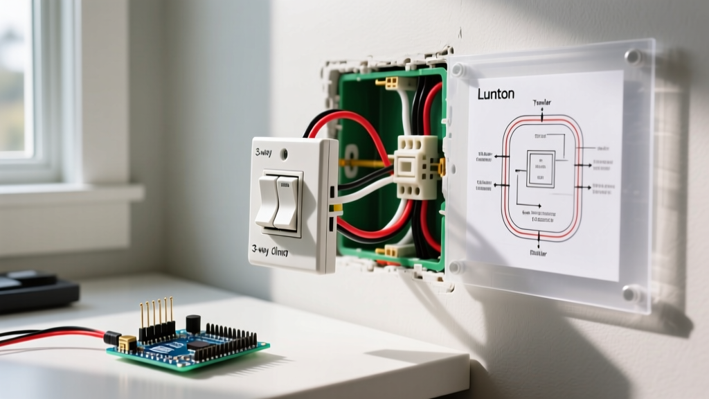
Interpreting a wiring diagram for Lutron 3 way dimmer circuits requires understanding that Lutron does not use traditional mechanical cross-switching. In a standard 3-way circuit, two mechanical switches alternate the path of electricity via two traveler wires. Lutron replaces this mechanical logic with electronic communication or wireless signals. When you upgrade to a Lutron LED+ dimmer (like the Diva or Maestro) or a smart Caséta system, the 'main' dimmer handles the actual phase-cutting dimming, while the secondary location acts as a companion switch or wireless remote.
The number one reason DIY installations fail—resulting in flickering LEDs, dead switches, or tripped breakers—is misidentifying the Line, Load, and Traveler wires. Before touching a wire nut, you must map your existing circuit. This guide breaks down the three most common Lutron 3-way wiring scenarios, complete with edge-case troubleshooting and National Electrical Code (NEC) compliance standards.
Scenario 1: Lutron Diva (DVCL-153P) with a Mechanical Companion
The Lutron Diva DVCL-153P is the industry standard for retrofit 3-way dimming, priced around $35-$40. Its massive advantage is that the main dimmer can be installed on either the Line (power source) or Load (light fixture) side of the circuit. The secondary location retains a standard mechanical 3-way toggle switch (included in the box).
Wiring the Main Diva Dimmer
- Green Wire: Connect to the bare copper or green ground wire in the wallbox. NEC Article 404.9 mandates that all snap switches be effectively grounded.
- Black Wires (2): On the DVCL-153P, the two black wires are interchangeable. One connects to your identified Line (constant hot) or Load (switched leg), and the other connects to the common terminal of the mechanical companion switch via a traveler wire.
- Blue Wires (2): These are the traveler wires. They connect directly to the two traveler terminals on the existing mechanical 3-way switch at the other location.
Wiring the Mechanical Companion
The companion switch remains standard. Connect the wall's remaining Line/Load wire to the 'Common' (usually a dark-colored screw) terminal. Connect the two Blue traveler wires from the Diva to the brass-colored traveler screws on the mechanical switch. Cap any unused wires with a wire nut and electrical tape.
Scenario 2: Lutron Maestro (MACL-153M) with the MA-R Companion
The Maestro MACL-153M (~$30) uses a digital tap-switch interface. Unlike the Diva, the Maestro system requires Lutron's proprietary MA-R electronic companion switch (~$25) at the secondary location. You cannot use a standard mechanical toggle with a Maestro main dimmer.
The Digital Traveler Handshake
In this scenario, the traveler wires do not carry full line voltage to the light. Instead, they carry a low-voltage digital communication signal between the MACL-153M and the MA-R.
- Main Dimmer (MACL-153M): Connect the Black wire to the Line/Load. Connect the Blue wires to the wall's traveler wires. Connect Green to Ground.
- Companion (MA-R): Connect the Black wire to the remaining Line/Load in the second box. Connect the Blue wires to the travelers. Connect Green to Ground.
Expert Edge Case: If your existing 3-way circuit uses a 'dead-end' 3-way setup (where the Line and Load are in the same box, and the second box only has travelers and a neutral), the standard Maestro wiring diagram will not work without pulling new 14/3 Romex. In this scenario, you must pivot to Scenario 3 (Wireless Pico).
Scenario 3: Caséta (PD-6WCL) and the Pico Wireless Bypass
The most robust solution for complex or poorly wired 3-way scenarios is the Lutron Caséta PD-6WCL (~$60) paired with a Pico PJ2-3BRL-WH-L01 remote (~$20) and a PICO-WBX-ADAPT wallbox adapter. This eliminates the need for traveler wires entirely.
Wiring the Main Caséta Dimmer
Install the Caséta dimmer in the box that contains both the Line and the Load, or use it to replace the switch on the Line side if the Load is routed through the ceiling. Connect Black to Line, Blue to Load, and Green to Ground. Cap off the old traveler wires with wire nuts; they are no longer needed.
Setting up the Pico Wallbox Adapter
At the secondary location, remove the old 3-way switch entirely. Cap the Line/Load and the traveler wires safely inside the wallbox. Mount the PICO-WBX-ADAPT over the wallbox using the provided screws, and snap the Pico remote into the adapter. The Pico communicates with the main Caséta dimmer via Lutron's proprietary Clear Connect RF protocol (434 MHz), completely bypassing the physical copper travelers.
The Critical Pre-Wiring Phase: Identifying Line, Load, and Travelers
Never guess wire functions based solely on insulation color. A previous electrician may have used white wires as hot travelers. To accurately map your circuit for any Lutron wiring diagram, follow this multimeter protocol:
- Turn off the breaker and remove both existing 3-way switches, leaving wires separated and safe.
- Turn the breaker back on. Use a non-contact voltage tester (NCVT) to identify which wires are 'hot'. The hot wire in Box A is your Line. If Box B has no hot wires, your Line is isolated to Box A.
- Identify Travelers: With the breaker off, use a multimeter set to continuity (ohms). Have a helper toggle the remaining mechanical switch while you test pairs of wires. The two wires that alternate continuity are your travelers.
- Identify the Load: The remaining wire in the system that leads up to the ceiling fixture is your Load.
Lutron 3-Way Dimmer Model Matrix
| Model Number | Max LED Load | 3-Way Companion Type | Avg. Cost (Main + Companion) | Best Use Case |
|---|---|---|---|---|
| Diva DVCL-153P | 150W | Standard Mechanical Toggle | $40 | Simple retrofits, standard 14/3 wiring |
| Maestro MACL-153M | 150W | MA-R Electronic Companion | $55 | Modern aesthetic, multi-location digital control |
| Caséta PD-6WCL | 150W | Pico Wireless Remote | $80 | Dead-end 3-ways, smart home integration |
Advanced Troubleshooting: Edge Cases and Failures
Even with a perfect wiring diagram execution, LED physics can cause anomalies. Here is how to resolve the most common Lutron 3-way dimmer failures:
1. LED Ghosting or Glowing When 'Off'
The Cause: Electronic dimmers like the Maestro and Caséta contain internal microprocessors that require a tiny amount of leakage current to remain powered for smart features or digital memory. With low-wattage LEDs (e.g., a single 9W bulb), this micro-current is enough to faintly illuminate the diodes.
The Fix: Install a Lutron LUT-MLC Minimum Load Capacitor (~$15). This inline capacitor is wired in parallel at the light fixture (across the hot and neutral), not at the switch. It absorbs the leakage current, providing the dummy load the dimmer requires without illuminating the bulb. For detailed installation parameters, always consult the Lutron Technical Support Portal.
2. Audible Buzzing at Mid-Range Dimming
The Cause: Incompatible LED drivers. Forward-phase (leading-edge) dimming chops the AC sine wave aggressively, causing cheap LED driver coils to vibrate physically.
The Fix: First, adjust the high-end and low-end trim settings on the Lutron dimmer to avoid the specific voltage phase angle that causes the resonance. If buzzing persists, the LED bulbs are not rated for forward-phase dimming. Swap to Lutron-tested LEDs (check the Lutron LED compatibility matrix) or upgrade to a reverse-phase (trailing-edge) dimmer like the Diva DVELV-300P.
3. Breaker Trips Upon Installation
The Cause: Miswired travelers or a shared neutral violation. If you connected a Lutron Blue traveler wire to a neutral bundle, you have created a direct short circuit the moment the mechanical companion is toggled.
The Fix: Re-verify your Line, Load, and Traveler mapping using the multimeter continuity test outlined above. Never assume wire colors dictate function in older homes.
NEC Compliance and Box Fill Constraints
When upgrading to Lutron 3-way dimmers, physical space is a major factor. The NEC (specifically NFPA 70 National Electrical Code, Article 314) dictates strict box fill calculations. Lutron dimmer bodies are exceptionally deep—often protruding 1.5 to 2.2 inches into the wallbox to accommodate heat sinks and internal electronics.
If you are working with shallow 14-cubic-inch 'pancake' boxes common in older construction, the dimmer body may crush the wires against the back of the box, damaging insulation and creating a severe fire hazard. The U.S. Consumer Product Safety Commission (CPSC) strongly warns against forced wire compression. If the dimmer does not seat flush without excessive force, install a 1-gang box extender ring (add-a-depth ring) to increase the cubic inch capacity and ensure safe heat dissipation.
Final Safety Verification
Before restoring power and snapping on the wallplate, perform a 'tug test' on every wire nut. Ensure no bare copper is exposed outside the nut. Verify that the green ground wire is securely bonded to the metal wallbox (if applicable) using a green grounding screw. Once power is restored, test the dimming range from both locations, adjusting the low-end trim dial until the LEDs operate without flickering or dropping out entirely.