
Understanding the London Electrical Outlet Standard (BS 1363)
When international electricians, expats, or DIY enthusiasts search for a London electrical outlet wiring guide, they are interfacing with one of the safest and most rigorously regulated socket standards in the world: the BS 1363 Type G system. Unlike North American NEMA configurations that rely on branch circuit breakers to protect appliance cords, the UK system integrates fuses directly into the plug, while the outlet itself features robust internal safety shutters and deep recesses.
Working in London presents unique challenges. The city's housing stock is a mix of modern builds, post-war reconstructions, and Victorian/Edwardian terraced homes. This means an electrician might encounter modern TN-C-S (PME) earthing in a new Canary Wharf apartment, but deal with a degraded TT earthing system in a 19th-century Camden terrace. Understanding the wiring diagram for a standard London electrical outlet requires mastering not just the socket termination, but the unique Ring Final Circuit (RFC) topology that dominates UK residential wiring.
Anatomy of a UK Type G Outlet
Before consulting the wiring diagram, it is critical to understand the physical and electrical anatomy of the BS 1363 socket. According to the Institution of Engineering and Technology (IET), all modern installations must comply with the 18th Edition of the Wiring Regulations (BS 7671:2018+A2:2022).
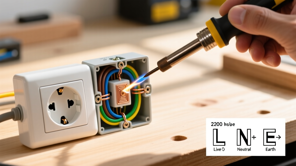
- Line (L): Brown insulation, connects to the right-hand terminal (when facing the socket).
- Neutral (N): Blue insulation, connects to the left-hand terminal.
- Earth (E / CPC): Bare copper with green/yellow sleeving, connects to the top central terminal.
- Safety Shutters: Mechanically operated by the longer Earth pin of a plugged-in device, preventing foreign object insertion into the Line or Neutral slots.
Ring Final vs. Radial Circuits: The UK Difference
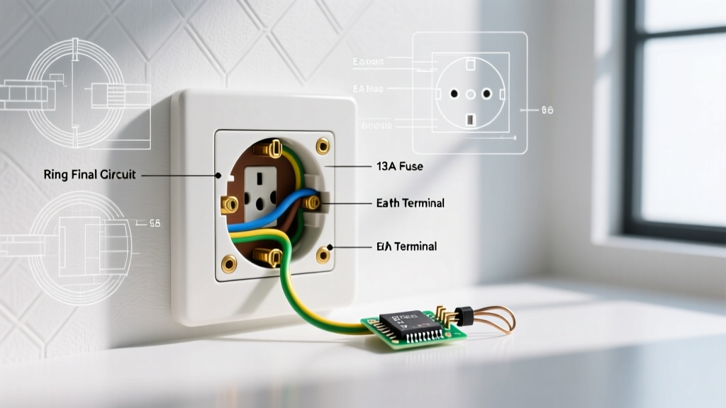
The most confusing aspect for foreign-trained electricians working on a London electrical outlet is the Ring Final Circuit. In a radial circuit (standard in the US and Europe), the cable runs from the consumer unit to the last outlet and stops. In a UK Ring Final Circuit, the cable leaves the consumer unit, loops through every socket on the floor, and returns to the same MCB (Miniature Circuit Breaker).
| Feature | Ring Final Circuit (RFC) | Radial Circuit |
|---|---|---|
| Cable Size | 2.5mm² Twin & Earth (T&E) | 4.0mm² T&E (for 32A) or 2.5mm² (for 20A) |
| MCB Rating | 32A (Type B or C) | 32A or 20A depending on cable |
| Topology | Continuous loop (In and Out at every socket) | Daisy-chain or star, ends at final socket |
| Max Floor Area | 100 square meters per ring | Unlimited, bound by voltage drop |
Step-by-Step Wiring Diagram Reference
Below is the definitive procedure for wiring a standard 13A double socket on a 2.5mm² Ring Final Circuit. Always ensure the circuit is isolated and locked off at the consumer unit before beginning.
1. Cable Preparation and Stripping
For a socket positioned in the middle of a ring, you will have two 2.5mm² T&E cables entering the backbox (the 'feed' and the 'return'). Strip the outer grey PVC sheath back to within 5mm of the backbox entry point to prevent the sheath from crowding the terminal enclosures. Strip the Line and Neutral insulation to exactly 8mm to ensure no bare copper is exposed outside the terminal brass, but no insulation is pinched inside the screw clamp.
2. Earth Sleeving (Mandatory)
The Circuit Protective Conductor (CPC) in standard UK T&E cable is bare copper. BS 7671 strictly mandates that this must be sleeved with green/yellow PVC tubing. In older London properties, you may find bare earth wires wrapped in green tape—this is non-compliant with modern standards and must be replaced with proper sleeving during any modification.
3. Terminal Termination
Because this is a ring circuit, the Line terminal will accept two brown wires and one jumper (if daisy-chaining to a spur, though spurs should be limited). Most modern BS 1363 socket terminals are designed with twin-tube or pillar terminals to safely clamp two 2.5mm² conductors side-by-side. Do not twist the wires together before insertion, as this can cause uneven clamping pressure and increase contact resistance.
4. Torque and Mounting
Tighten the terminal screws firmly. While BS 7671 does not specify an exact Nm torque for standard 13A socket terminal screws, industry best practice dictates using a calibrated torque screwdriver set to approximately 0.5Nm to 0.8Nm to prevent stripping the brass threads while ensuring a gas-tight connection. When mounting the faceplate, use the 3.5mm x 25mm machine screws provided, ensuring the earth wire is not pinched between the faceplate and the plasterboard.
London Part P Compliance Warning: Under Part P of the Building Regulations (which applies in England, including London), adding a new socket circuit or working in 'special locations' (like bathrooms or outdoors) is notifiable to Local Authority Building Control. Simply replacing a damaged faceplate or adding a socket to an existing ring in a standard living room is generally non-notifiable, but must still be tested and certified with a Minor Electrical Installation Works Certificate (MEIWC).
Advanced Troubleshooting: London-Specific Edge Cases
When testing a newly wired London electrical outlet, you must verify the Earth Fault Loop Impedance (Zs). According to Electrical Safety First, the Zs must be low enough to ensure the 32A MCB trips within the required 0.4 seconds for socket outlets.
High Zs in Victorian Terraces
In many older London boroughs (e.g., Islington, Hackney), properties rely on a TT earthing system where the earth is provided by a local earth rod rather than the utility supplier. If you measure a high Ze (external earth loop impedance) often exceeding 200 ohms, a standard 30mA RCD or RCBO is mandatory to provide fault protection, as the MCB alone will not trip fast enough. Always verify the earthing arrangement before assuming a standard Type B MCB provides adequate indirect contact protection.
Polarity and Open Neutrals
Because ring circuits return to the consumer unit, an open neutral on the 'return' leg might not immediately manifest as a dead socket. The socket may still function via the 'feed' leg, but the remaining sockets on the ring will now be operating on a single 2.5mm² cable protected by a 32A breaker, creating a severe fire risk due to potential cable overload. Always perform a full Ring Final Circuit continuity test (measuring r1, rn, and r2) and figure-of-eight polarity tests before energizing.
Frequently Asked Questions
Can I wire a US appliance directly into a London electrical outlet?
No. London outlets supply 230V at 50Hz. North American appliances designed for 120V/60Hz will be destroyed and pose a fire hazard if plugged in, even with a physical adapter. You must use a step-down transformer rated for the appliance's wattage, or verify the appliance has a universal switch-mode power supply (100-240V).
How many spurs can I add to a London ring circuit?
BS 7671 dictates that you can have an unlimited number of spurs on a ring final circuit, provided that the number of spurs does not exceed the total number of sockets on the ring, and each unfused spur feeds only one single or one double socket. Alternatively, you can use a Fused Connection Unit (FCU) rated at 13A to feed an unlimited number of additional sockets on that specific spur.
Why are London outlets so bulky compared to European ones?
The BS 1363 standard requires significant internal volume to accommodate the safety shutters, the deep recess to prevent finger contact with plug pins, and the robust terminal blocks required to safely clamp two 2.5mm² cables for ring wiring. This necessitates deeper wall backboxes, typically 35mm or 47mm deep, compared to the shallow boxes used in many EU countries.