
Wiring Diagram Reference: Exterior Outlet Installation
Installing an outdoor receptacle requires more than just running a wire through a wall. Exterior environments subject electrical components to UV degradation, extreme temperature fluctuations, condensation, and physical impact. According to the National Fire Protection Association (NFPA), outdoor electrical failures remain a leading cause of residential shock hazards, which is why modern electrical codes enforce strict GFCI, AFCI, and weather-resistance mandates.
This comprehensive wiring diagram reference breaks down exactly how to install exterior electrical outlet circuits safely. We will cover schematic node maps for both interior GFCI extensions and dedicated panel circuits, outline the precise materials required for wet locations, and detail the physical conduit routing techniques that prevent moisture ingress and nuisance tripping.
Essential Materials & Cost Breakdown
Using indoor-rated materials outdoors is a critical failure point. Standard nylon faceplates crack under UV exposure, and standard brass terminals corrode rapidly in humid environments. Below is the exact bill of materials required for a code-compliant, long-lasting exterior outlet installation.
| Component | Recommended Model / Specification | Purpose & Code Requirement | Est. Cost |
|---|---|---|---|
| Receptacle | Hubbell 5262-WR (20A TR Duplex) | Weather-Resistant (WR) and Tamper-Resistant (TR) per NEC 406.9(A). | $14.50 |
| In-Use Cover | TayMac ML500 Extra-Deep Die-Cast | Allows cords to remain plugged in while sealed from rain per NEC 406.9(B). | $22.00 |
| Conduit & Fittings | 1/2" Schedule 80 PVC & LB Fitting | Schedule 80 required where subject to physical damage (NEC 352.10). | $35.00 |
| Wire (Conduit Run) | 12 AWG THWN-2 (Stranded) | Rated for wet locations; stranded pulls easier through PVC bends. | $0.85/ft |
| Sealant | GE Silicone II (Clear or Paintable) | 100% silicone waterproof seal for siding penetrations and cover gaskets. | $8.50 |
| Circuit Breaker (If new) | Square D HOM220GFIC (Dual Function) | Combines AFCI and GFCI protection for dedicated 20A outdoor circuits. | $58.00 |
Note: Total material costs for a standard single-outlet extension range from $85 to $150. Hiring a licensed electrician typically costs between $250 and $450, depending on siding penetration complexity and panel access.
Core Wiring Schematics for Outdoor Receptacles
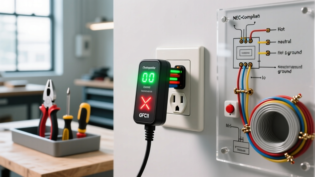
Because visual blueprints cannot capture the nuance of terminal torque and wire preparation, we utilize structured Schematic Node Maps. These maps dictate the exact line-to-load routing required for safe outdoor power delivery.
Diagram A: Extending from an Interior GFCI (Load-Side Feed)
This is the most common retrofit scenario. You are tapping into an existing indoor GFCI receptacle (like a kitchen or garage outlet) to feed a new exterior outlet. The interior GFCI provides the required ground-fault protection, allowing you to use a standard WR receptacle outside.
Schematic Node Map: Interior GFCI to Exterior WR Receptacle
1. Power Source (12/2 NM-B) to Interior GFCI LINE Terminals:
- Black (Hot) → Brass LINE Screw (Torque to 14 in-lbs)
- White (Neutral) → Silver LINE Screw
- Bare (Ground) → Green Ground Screw + Pigtail to Metal Box
2. Interior GFCI LOAD Terminals to Exterior Conduit (12 AWG THWN-2):
- Black THWN-2 → Brass LOAD Screw (Feeds downstream protection)
- White THWN-2 → Silver LOAD Screw
- Green THWN-2 → Green Ground Screw (Daisy-chained with source ground)
3. Exterior WR Receptacle (Hubbell 5262-WR) Termination:
- Black THWN-2 → Brass Terminal (Side-wired, 3/4" strip length. Never use backstab push-in connections outdoors.)
- White THWN-2 → Silver Terminal
- Green THWN-2 → Green Ground Terminal + Pigtail to Weatherproof Box
Diagram B: Dedicated 20A Circuit from the Main Panel
If you are installing high-draw outdoor equipment (e.g., patio heaters, pond pumps, or EV trickle chargers), a dedicated 20A circuit is mandatory. This requires running individual THWN-2 conductors through PVC conduit from the main service panel to the exterior.
Schematic Node Map: Panel to Exterior (Dual-Function Breaker)
1. Main Panel Termination (Square D HOM220GFIC Breaker):
- Black THWN-2 → Breaker Hot Terminal Lug
- White THWN-2 → Breaker Neutral Terminal Lug (Do NOT land on the neutral bus bar)
- Breaker Coiled White Pigtail → Panel Neutral Bus Bar
- Green THWN-2 → Panel Equipment Grounding Bus Bar
2. Exterior Weatherproof Box & WR Receptacle:
- Black THWN-2 → Receptacle Brass Terminal
- White THWN-2 → Receptacle Silver Terminal
- Green THWN-2 → Receptacle Ground Screw + Box Grounding Screw
Critical NEC Code Requirements (2023/2026 Editions)
The National Electrical Code (NEC) updates continuously to address outdoor electrical hazards. When planning your wiring diagram, ensure your design complies with the following articles, heavily enforced by local inspectors and cited by the U.S. Consumer Product Safety Commission (CPSC) as vital for shock prevention.
NEC Article 210.8(F) - GFCI Protection: All 125-volt through 250-volt receptacles supplied by single-phase branch circuits rated 150 volts or less to ground, 50 amperes or less, installed outdoors must have ground-fault circuit-interrupter protection for personnel. There are no longer exceptions for dedicated snow-melting equipment outlets on residential properties.
NEC Article 406.9(A) & (B) - Weather Resistance & In-Use Covers: All 15A and 20A receptacles installed in damp or wet locations must be listed as Weather-Resistant (WR) and Tamper-Resistant (TR). Furthermore, an in-use cover must be installed that maintains the weatherproof seal whether a plug is inserted or not.
Physical Routing: Siding Penetration & Conduit Slope
A perfect wiring diagram will fail if the physical installation allows water to migrate into the junction box. Condensation is the silent killer of outdoor GFCI circuits. Follow these precise physical routing steps:
- Drill the Rim Joist Penetration: Use a 5/8" spade bit or auger bit to drill through the exterior siding and rim joist from the outside in. Angle the drill bit slightly upward (about 5 degrees) so the interior hole is higher than the exterior hole. This creates a natural gravity dam against wind-driven rain.
- Install the LB Conduit Body: Mount a 1/2" PVC LB fitting flush against the siding. Before securing it with stainless steel screws, apply a thick bead of GE Silicone II to the back edge of the LB body to create a watertight gasket against the siding.
- Establish the Conduit Slope: When routing the PVC conduit downward to the receptacle box, maintain a strict slope of 1/4 inch per foot outward. This ensures that any condensation that forms inside the conduit drains away from the house and out the bottom of the exterior box.
- Drill a Weep Hole: Using a 1/8" drill bit, bore a small weep hole at the absolute lowest point of the exterior weatherproof box (usually the bottom knockout). This allows trapped moisture to escape rather than pooling around the WR receptacle terminals.
- Pull and Terminate THWN-2: Use stranded THWN-2 wire for conduit pulls. Stranded wire handles the thermal expansion and contraction of outdoor PVC conduit far better than solid NM-B romex, which is strictly prohibited inside outdoor conduit due to moisture wicking.
Troubleshooting Nuisance GFCI Trips Outdoors
If your newly installed exterior outlet trips immediately or during rainstorms, the issue is rarely a defective breaker. It is almost always an installation error related to moisture or wiring topology. Use this diagnostic matrix to identify the failure mode:
- Failure Mode 1: Shared Neutrals (Multi-Wire Branch Circuits). If you extended power from an interior circuit that shares a neutral with another hot leg, the GFCI will detect the returning current on the shared neutral as an imbalance and trip instantly. Solution: Ensure the exterior GFCI circuit has a dedicated, isolated neutral all the way back to the panel.
- Failure Mode 2: Moisture Wicking via NM-B Cable. If standard indoor Romex (NM-B) was run through outdoor PVC conduit, the paper wrapping inside the cable acts like a sponge, wicking condensation directly into the interior wall cavity and the GFCI terminals. Solution: Cut back the NM-B to inside the house, transition to a junction box, and run individual THWN-2 wires through the exterior conduit.
- Failure Mode 3: Line vs. Load Reversal. If the exterior receptacle is a GFCI itself (fed from a standard interior breaker) and it won't reset or provide power, the feed wires are likely connected to the LOAD terminals instead of the LINE terminals. Solution: Use a non-contact voltage tester to identify the incoming hot wire and move it to the brass LINE terminal.
- Failure Mode 4: Gasket Compression Failure. The foam gasket on the TayMac in-use cover may not be sealing properly if the siding is uneven (like cedar shakes or stucco). Solution: Apply a continuous bead of silicone caulk around the top and sides of the cover plate, leaving the bottom edge uncaulked to allow any internal condensation to drain.
By adhering to these wiring diagram schematics, utilizing wet-location rated materials, and executing precise physical conduit routing, your exterior electrical outlet will provide safe, reliable, and code-compliant power for years to come.