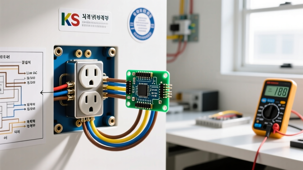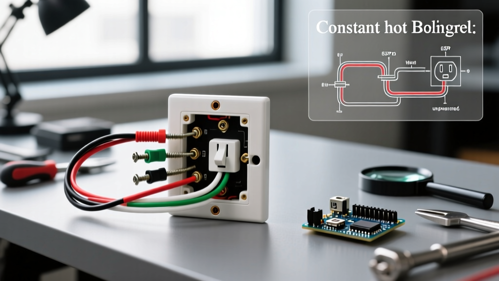

Understanding the Constant Hot Electrical Outlet
When tackling residential electrical projects, beginners often confuse switched receptacles with a constant hot electrical outlet. A constant hot outlet (also known as an unswitched or always-hot receptacle) receives uninterrupted 120V power directly from the circuit breaker. Unlike a half-hot outlet—where one half is controlled by a wall switch for a lamp—a constant hot outlet ensures both the top and bottom duplex receptacles are live at all times. This is the standard configuration for kitchen countertops, garage workbenches, and general living room walls.
In this comprehensive beginner tutorial, we will walk through the exact process of wiring a standard 15-amp constant hot electrical outlet. We will focus on industry-best practices, National Electrical Code (NEC) compliance, and the specific mechanical techniques that prevent arc faults and heat buildup over time.
Required Tools and Materials (2026 Pricing & Models)
Using the right tools is non-negotiable for electrical safety and connection integrity. Here is the exact bill of materials for a standard 15-amp, 120-volt branch circuit:
- Receptacle: Leviton 15 Amp Tamper-Resistant (TR) Duplex Outlet (Model: R52-05320-WMP). Cost: ~$2.15 per unit. As mandated by NEC Article 406.12, all 15A and 20A receptacles in dwelling units must be tamper-resistant to prevent childhood shock hazards.
- Wire Strippers: Klein Tools 11055 Automatic Wire Stripper (Model: 11055). Cost: ~$28.00. Provides clean strips without nicking the copper conductor.
- Voltage Tester: Fluke 1AC-II VoltAlert Non-Contact Voltage Tester. Cost: ~$35.00. Essential for verifying a dead circuit before touching any bare copper.
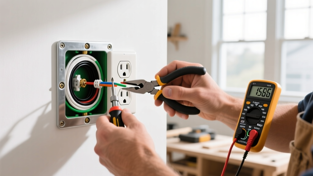
- Pliers: Lineman pliers and needle-nose pliers for forming terminal hooks.
- Connectors: Ideal 341 Orange Wire Nuts (for 14 AWG to 12 AWG pigtailing).
Safety First: Verifying the Dead Circuit
CRITICAL SAFETY WARNING: Never assume a circuit is dead based on a wall switch position or a tripped GFCI downstream. According to the U.S. Consumer Product Safety Commission (CPSC), electrical shocks and residential fires frequently occur when DIYers fail to verify the absence of voltage at the specific termination point. Always test at the bare wires.
- Locate your main electrical panel and switch the target 15A or 20A breaker to the OFF position.
- Remove the existing outlet cover plate and unscrew the receptacle from the junction box.
- Insert the tip of your Fluke 1AC-II tester into the slots of the old outlet, then touch it directly to the bare copper ground wire and the black (hot) wire insulation. The tester must remain completely dark and silent.
Step-by-Step Installation Guide
Step 1: Prepare the Junction Box and Wires
Pull the Romex (NM-B) cable out of the junction box. You should see three wires: a black (hot), a white (neutral), and a bare copper (ground). Using your Klein Tools 11055 strippers, strip exactly 3/4 of an inch of insulation from the black and white wires. This specific measurement matches the strip gauge found on the back of the Leviton R52-05320-WMP receptacle, ensuring no bare copper is exposed outside the terminal, and no insulation is trapped under the screw head.
Step 2: Form the Terminal J-Hooks
Using your needle-nose pliers, grip the stripped end of the black wire and bend it into a tight 'J' or shepherd's hook shape. Repeat this for the white and bare copper wires. The hook should be perfectly round to match the curvature of the terminal screw.
Step 3: Connect the Ground (Green Screw)
Loop the bare copper J-hook around the green grounding screw at the bottom of the receptacle. Crucial detail: The hook must face clockwise. When you tighten the screw clockwise, the loop will naturally close and tighten around the shaft. If hooked counter-clockwise, the screw will push the wire out from under the head, creating a high-resistance open ground fault.
Step 4: Connect the Neutral (Silver Screw)
Attach the white (neutral) wire J-hook to one of the silver-colored screws on the left side of the receptacle. Again, ensure the hook faces clockwise. Tighten the screw firmly until the brass/silver plate clamps down securely on the wire. Give the wire a gentle tug to ensure mechanical stability.
Step 5: Connect the Hot Wire (Brass Screw)
This is the defining step for your hot electrical outlet. Take the black (hot) wire and loop it clockwise around one of the brass-colored screws on the right side of the receptacle. The brass side is always the 'hot' or 'line' side. Tighten the screw securely. Because we are wiring a constant hot outlet, ensure the small brass break-off fin (tab) connecting the top and bottom brass screws remains completely intact. Breaking this tab is only done for split-wired (switched) outlets.
Step 6: Secure and Test
Carefully fold the wires back into the junction box. Push the receptacle flush against the box and secure it with the provided 6-32 machine screws. Attach the cover plate, restore power at the breaker panel, and test both the top and bottom receptacles with a standard 3-prong outlet tester to confirm correct wiring.
Connection Methods: Side-Wiring vs. Backstabbing
Beginners often look at the back of the receptacle and see push-in holes (backstabbing). While faster, professional electricians universally avoid this method for a constant hot electrical outlet. Below is a technical comparison of the two methods based on thermal performance and mechanical grip.
| Feature | Side-Wiring (Screw Terminals) | Backstabbing (Push-In Connectors) |
|---|---|---|
| Wire Gauge Accepted | 14 AWG and 12 AWG solid copper | 14 AWG solid copper ONLY |
| Connection Mechanism | Mechanical screw clamp with high surface area | Internal spring-loaded metal tang |
| Thermal Performance | Excellent; low resistance, minimal heat | Poor; prone to arcing and heat buildup under heavy load |
| Failure Rate | Extremely low (industry standard) | High; springs loosen over time due to thermal cycling |
| Recommended Use | All permanent residential installations | None (strictly avoided by professionals) |
Always use the side-wiring screw terminals. The mechanical pressure of the screw provides a gas-tight connection that resists the thermal expansion and contraction that occurs when high-draw appliances (like space heaters or vacuum cleaners) are plugged into the outlet.
Common Beginner Mistakes and Troubleshooting
Mistake 1: Reversed Polarity
Connecting the black hot wire to the silver screw and the white neutral to the brass screw results in reversed polarity. While the appliance may still turn on, the internal fuse or switch of the plugged-in device will only disconnect the neutral path, leaving the internal components energized at 120V even when turned off. This is a severe shock hazard. Always remember: Black to Brass (Hot), White to Silver (Neutral).
Mistake 2: Over-Stripping the Wire
Stripping more than 3/4 inch of insulation leaves bare copper exposed outside the terminal block. If the hot and neutral bare wires are close to each other, or if a bare hot wire touches the metal junction box, it will cause a dead short and trip the breaker instantly. Use the strip gauge printed on the back of the Leviton receptacle to measure your cuts.
Mistake 3: Ignoring GFCI Requirements
As outlined in the National Fire Protection Association (NFPA) 70: National Electrical Code, standard duplex outlets are not permitted in wet or damp locations. If you are installing an outlet in a bathroom, garage, unfinished basement, or within 6 feet of a kitchen sink, you must upgrade to a Ground Fault Circuit Interrupter (GFCI) receptacle, such as the Leviton 15A SmartlockPro GFCI (Model: R52-08895-WMP, approx. $16.50).
Frequently Asked Questions (FAQ)
Q: Can I use a 20-amp receptacle on a 15-amp circuit?
A: No. NEC Article 210.21(B)(1) dictates that on a 15-amp branch circuit, you must use 15-amp rated receptacles. However, you can use 15-amp receptacles on a 20-amp circuit, provided the circuit supplies more than one outlet.
Q: Why does my outlet tester show an 'Open Ground'?
A: An open ground means the bare copper wire is not making a continuous path back to the main panel's grounding bus bar. Check that your J-hook is tightly secured under the green screw and that the ground wire is properly spliced to the incoming ground in the junction box.
Q: Do I need to wrap electrical tape around the sides of the outlet?
A: While not strictly required by the NEC if the screw terminals are properly tightened and the box is adequately sized, many master electricians wrap the sides of the receptacle with Super 33+ vinyl electrical tape. This 'mudding' tape prevents accidental shorts if the bare ground wire shifts and touches the side terminal screws during the push-back into a crowded junction box.