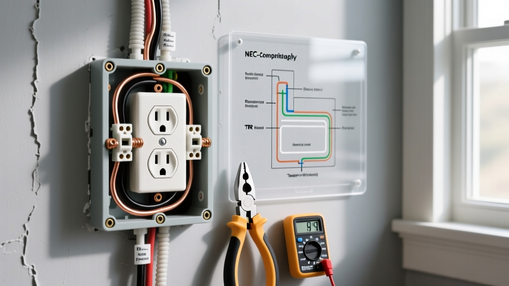

Introduction to Safe Receptacle Wiring
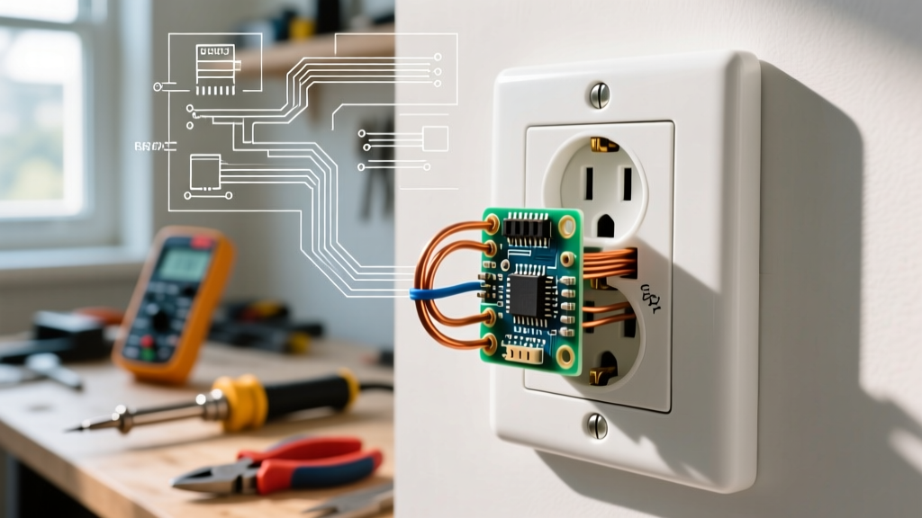
Understanding an electrical outlet wiring diagram is the foundational skill for any DIYer or apprentice electrician. However, simply connecting wires to terminals is not enough; modern electrical work demands strict adherence to the National Electrical Code (NEC) and rigorous safety protocols. As jurisdictions continue to adopt the NEC 2023 and transition into the 2026 code cycle, the tolerances for improper installations have narrowed significantly. This guide transcends basic tutorials by integrating code compliance, precise torque specifications, and advanced troubleshooting into your wiring workflow.
According to the National Fire Protection Association (NFPA), electrical distribution and lighting equipment are consistently among the leading causes of home structure fires. Properly interpreting and executing an electrical outlet wiring diagram mitigates these risks by ensuring secure connections, correct polarity, and effective fault-current paths.
The Anatomy of a Standard Electrical Outlet Wiring Diagram
A standard 120-volt, 15-amp or 20-amp duplex receptacle wiring diagram features three primary conductors. Misidentifying these or reversing their terminals is a leading cause of shock hazards and equipment damage.
- Hot (Line) Conductor: Typically black or red insulation. Connects to the brass-colored terminal screw. This wire delivers the 120V alternating current from the breaker panel.
- Neutral Conductor: Typically white or gray insulation. Connects to the silver-colored terminal screw. This wire completes the circuit, carrying current back to the source.
- Equipment Grounding Conductor (EGC): Bare copper or green insulation. Connects to the green grounding screw. This is a critical safety path that directs fault current to the earth, tripping the breaker in the event of a short circuit.
Safety Warning: Never rely solely on wire color. Previous installations may have used incorrect colors or switched loops. Always verify the absence of voltage using a Category III (CAT III) or Category IV (CAT IV) non-contact voltage tester or a digital multimeter before touching any conductor.
NEC Code Compliance: What the Basic Diagram Doesn't Show
A generic electrical outlet wiring diagram rarely illustrates the nuanced code requirements for specific rooms. The NEC mandates specialized protection depending on the receptacle's location and proximity to water or living spaces.
Mandatory Tamper-Resistant Receptacles (TRR)
Under NEC Section 406.12, all 15-amp and 20-amp, 125-volt and 250-volt non-locking receptacles installed in dwelling units must be tamper-resistant. TRRs feature internal spring-loaded shutters that only open when equal pressure is applied to both slots simultaneously. The Consumer Product Safety Commission (CPSC) notes that TRRs prevent thousands of childhood shock injuries annually. When purchasing, look for the 'TR' stamp on the face of the yoke. Standard models like the Leviton T5320-W (approx. $3.50) or commercial-grade Hubbell HBL5362 (approx. $9.00) are industry staples.
Receptacle Protection Matrix (NEC 2023/2026)
| Location | Required Protection | NEC Reference | Device Type Needed |
|---|---|---|---|
| Kitchens (Countertop) | GFCI & AFCI | 210.8(A)(6) & 210.12(A) | 20A GFCI Receptacle or GFCI Breaker + AFCI Breaker |
| Bathrooms | GFCI | 210.8(A)(1) | 20A GFCI Receptacle |
| Bedrooms & Living Rooms | AFCI | 210.12(A) | Standard TRR on an AFCI Breaker |
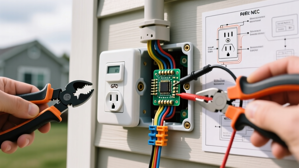
| Garages & Outdoors | GFCI | 210.8(A)(2) & (3) | 20A Weather-Resistant (WR) GFCI |
| Laundry Areas | GFCI & AFCI | 210.8(A)(10) & 210.12(A) | 20A GFCI Receptacle + AFCI Breaker |
Precision Execution: Torque, Stripping, and Looping
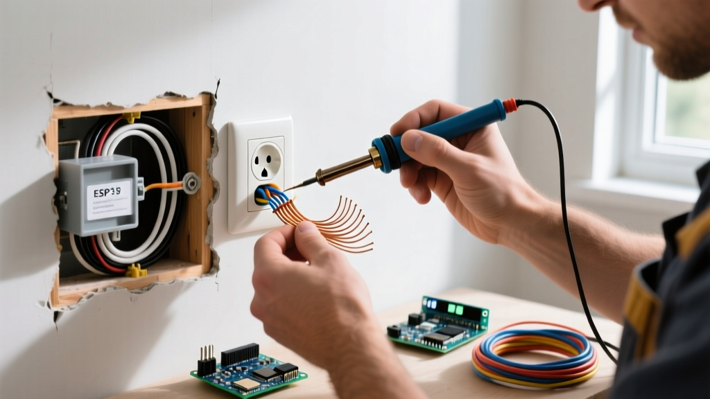
The most critical failure point in outlet wiring is a loose termination. A loose connection increases electrical resistance, generating heat that can melt the yoke and ignite surrounding framing. To prevent this, you must follow precise mechanical steps.
1. Wire Stripping Specifications
Use the built-in strip gauge on the back of the receptacle. For most 15A and 20A devices, the bare wire must be stripped to exactly 5/8 inch to 3/4 inch. Stripping too little leaves insulation under the terminal screw (causing a high-resistance open circuit). Stripping too much exposes bare copper outside the terminal, creating a shock and short-circuit hazard.
2. The Clockwise Loop Rule
When using side-wiring (screw terminals), form a J-hook in the solid copper wire using needle-nose pliers. Place the loop around the screw so that the open end of the 'J' faces clockwise. As you tighten the screw, the rotational force pulls the loop tighter around the shaft. A counter-clockwise loop will be pushed out from under the screw head as it tightens.
3. Torque Screwdriver Requirements
Modern NEC guidelines and manufacturer instructions increasingly require calibrated torque. For standard 15A and 20A receptacles, manufacturers like Leviton and Hubbell specify a terminal screw torque of 14 inch-pounds (1.58 Nm). Using a calibrated torque screwdriver, such as the Ideal Industries 61-174 or Klein Tools 695 (retailing around $120-$150), ensures the screw is tight enough to prevent arcing but not so tight that it strips the brass threads or snaps the screw head.
4. Back-Wiring vs. Push-In Terminals
Never use the push-in 'stab' connections on the back of standard 15A receptacles. These rely on a small internal brass spring clip that loses tension over time due to thermal expansion and contraction, leading to catastrophic failures. Instead, use the back-wire clamp plates found on commercial-grade or spec-grade receptacles. These plates are physically clamped down by the terminal screw, providing a secure, high-surface-area connection that easily accepts two wires per terminal.
Advanced Diagram Variations: Split-Wired Kitchen Receptacles
A standard electrical outlet wiring diagram assumes both the top and bottom duplex halves are on the same circuit. However, kitchen countertop receptacles often require a split-wired configuration. This allows the top half to be on Circuit A and the bottom half on Circuit B, ensuring that running a microwave and a toaster simultaneously does not trip a single 20-amp breaker.
Execution Steps for Split-Wiring:
- Identify the brass (hot) terminal side of the duplex receptacle.
- Locate the small metal connecting tab (fin) between the top and bottom brass screws.
- Using lineman's pliers, grip the tab and snap it off. Do not break the silver (neutral) tab; the neutral must remain shared and bonded across both halves.
- Connect the black wire from Circuit A to the top brass screw, and the red wire from Circuit B to the bottom brass screw.
- Connect the shared white neutral to the silver screw and the bare ground to the green screw.
- Code Note: Both circuits must be fed from a double-pole breaker or have identified handle ties to ensure simultaneous disconnect, per NEC 210.4(B).
Verification: Testing the Installation
Once the receptacle is secured to the electrical box and the faceplate is installed, you must verify the wiring. Do not rely on visual inspection alone. Use a professional-grade receptacle tester, such as the Amprobe AT-3500 or the Gardner Bender GRT-100.
Insert the tester into the top and bottom slots. The LED indicator pattern will confirm:
- Correct Wiring: Typically two amber lights (verify with your specific tester's legend).
- Open Ground: The EGC is disconnected. Fault current has no path to trip the breaker.
- Reversed Polarity: Hot and neutral are swapped. The shell of a plugged-in lamp will be energized, presenting a severe shock hazard.
- Hot/Ground Reverse: A dangerous miswire that energizes the grounding system.
For GFCI receptacles, press the 'TEST' button on the tester to ensure the internal solenoid trips the mechanism and cuts power, verifying the ground-fault protection is active.
Frequently Asked Questions (FAQ)
Can I use 14 AWG wire on a 20-amp circuit?
No. NEC Section 240.4(D) strictly limits 14 AWG copper wire to a maximum 15-amp overcurrent device. If you are wiring a 20-amp circuit (common in kitchens, bathrooms, and garages), you must use a minimum of 12 AWG copper wire and a 20-amp rated receptacle. Installing a 15-amp receptacle on a 20-amp circuit is permitted only if it is a duplex receptacle, but the wiring feeding it must still be 12 AWG.
What happens if the electrical box is not grounded?
If you are replacing an existing two-prong receptacle in an older home with no equipment grounding conductor, NEC 406.4(D)(2) provides specific solutions. You cannot simply install a standard three-prong receptacle. You must either install a GFCI receptacle (labeled 'No Equipment Ground'), or run a new EGC back to the panel. The Occupational Safety and Health Administration (OSHA) heavily emphasizes the necessity of proper grounding pathways in all electrical environments to prevent fatal shocks.
Why do my wires keep slipping out of the terminal screws?
This usually occurs because the wire was not stripped far enough, causing the insulation to bind against the yoke before the copper is fully seated under the screw head. Alternatively, if using stranded wire, it must be tinned with solder or fitted with a crimp-on ferrule; wrapping bare stranded wire around a screw often results in strands fraying and escaping the termination point.
Conclusion
Mastering the electrical outlet wiring diagram is about more than memorizing which color goes to which screw. It requires a disciplined approach to mechanical execution, an understanding of modern NEC mandates like TRR and AFCI/GFCI protection, and the use of precision tools like torque screwdrivers. By treating every installation as a critical safety system rather than a simple connection, you ensure long-term reliability and protect your home from electrical hazards. Always consult a licensed electrician if you encounter aluminum wiring, ungrounded systems, or panel-level modifications beyond your scope of expertise.