
The Shift to LED Dimming: Why Your Old Toolkit Falls Short
Transitioning from incandescent to solid-state lighting fundamentally changes the physics of your wall switch. When you consult a standard wiring diagram for led dimmer switch setups, you are no longer just choking voltage with a simple TRIAC; you are managing pulse-width modulation (PWM) or high-frequency phase-cut signals. In 2026, with the widespread adoption of Matter-over-Thread smart dimmers and ultra-low-wattage LED drivers, the margin for wiring error is virtually zero. A poorly terminated neutral or an undersized wire nut will result in ghosting, audible buzzing, or catastrophic driver failure.
This guide strips away the fluff and provides a professional-grade tool and material checklist, alongside a precise wiring logic matrix, to ensure your LED dimmer installation meets both NEC standards and manufacturer specifications.
The 2026 Electrician’s Toolkit for LED Dimming
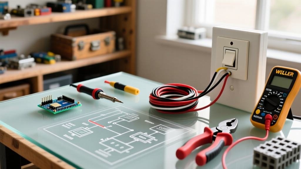
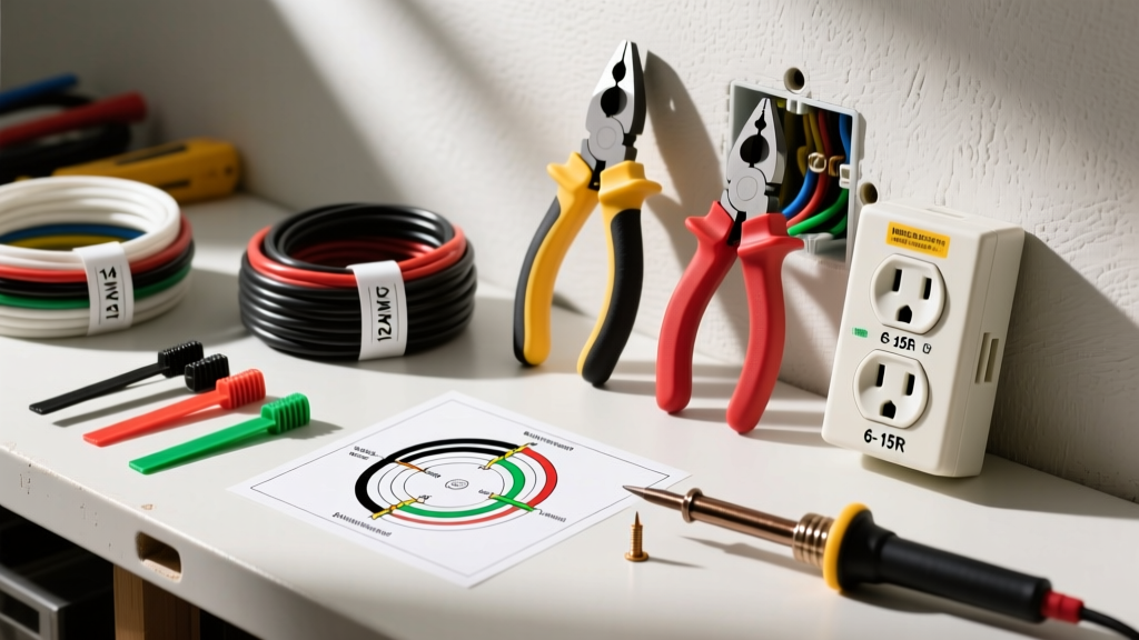
Standard diagonal cutters and lineman pliers are insufficient for modern smart dimmers. The internal electronics of a $65 smart dimmer require precise termination to prevent heat buildup and signal degradation.
- Wire Strippers: Klein Tools 11055 (10-18 AWG). Clean, nick-free stripping is mandatory. A nicked 14 AWG copper conductor creates a high-resistance hotspot behind the yoke.
- Non-Contact Voltage Tester: Fluke 1AC-II VoltAlert. Essential for verifying the absence of voltage on both line and load conductors before touching a single wire.
- Torque Screwdriver: Wiha TorqueVario or Klein Tools 32500INS. Per NEC 110.14(D), terminals marked with torque values must be tightened to spec. Most Lutron and Leviton LED dimmers require exactly 14 to 16 in-lbs.
- Wire Connectors: Ideal 33-071 (Tan) or 33-091 (Yellow) Wire-Nuts. Avoid cheap, unbranded connectors. The internal coil must bite firmly into the copper to handle the inrush current of LED drivers.
Material Selection Matrix: Top LED Dimmers
Not all dimmers are created equal. Selecting the wrong model for your specific LED bulb type (e.g., using a forward-phase dimmer on an ELV transformer) guarantees flickering. Below is a comparison of the top-performing LED dimmers on the market in 2026.
| Model | Dimming Type | Min. Load | Neutral Required? | Est. Price (2026) |
|---|---|---|---|---|
| Lutron Diva DVCL-153P | Forward/Reverse Phase (Auto) | 1 LED / 15W | No (but recommended) | $28 - $32 |
| Leviton Decora DW6HD | Forward Phase (TRIAC) | 1 LED / 10W | Yes (Mandatory) | $45 - $55 |
| Lutron Caseta PD-6WCL | Forward Phase (Smart/RF) | 1 LED / 17W | No (Uses patented tech) | $60 - $68 |
| Eaton HALO-RL | Reverse Phase (ELV) | 10W | Yes | $35 - $42 |
Pro Tip: Always verify your bulb's compatibility using the Lutron LED Compatibility Tool before purchasing. Manufacturers test specific bulb-driver pairings to eliminate micro-flicker.
Decoding the Wiring Diagram for LED Dimmer Switch
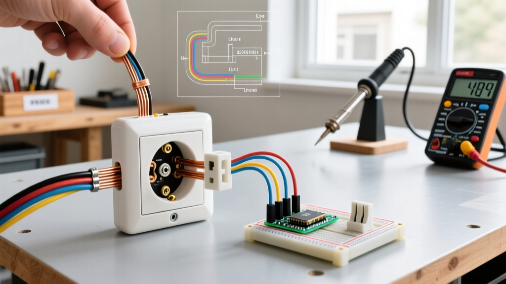
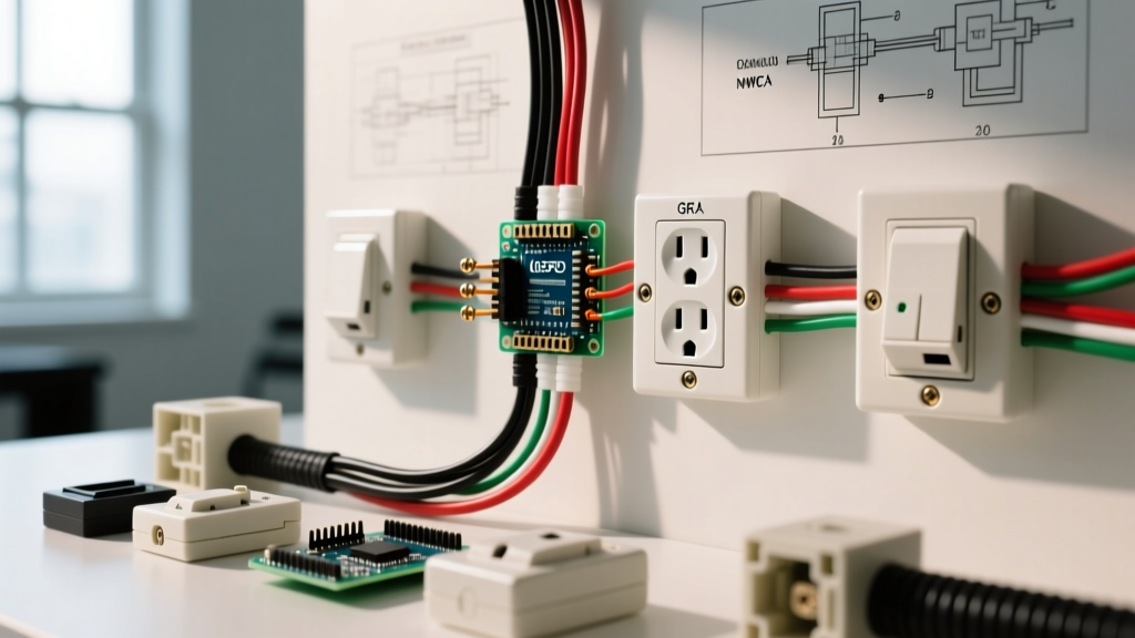
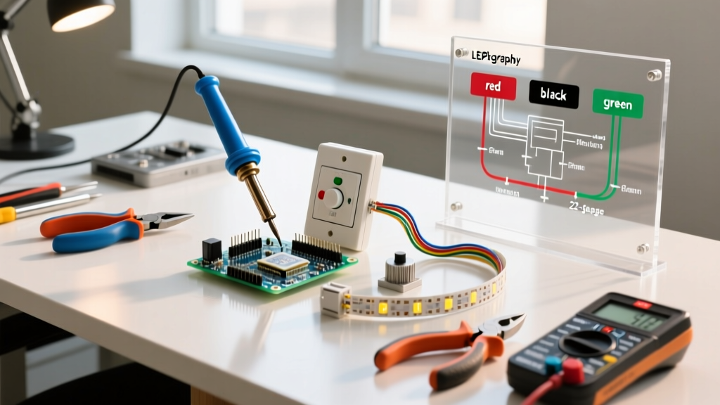
Unlike legacy incandescent switches that simply broke the hot leg, modern LED dimmers require a complete circuit to power their internal microprocessors and Wi-Fi/Thread radios. Understanding the wiring diagram for led dimmer switch configurations hinges on identifying four distinct conductors.
1. The Line (Hot) Conductor
This is the incoming power from your breaker panel. It is typically black (or red in 3-way setups). It connects to the Line terminal on the dimmer. Use your Fluke tester to identify this wire; it will show 120V to ground when the breaker is on.
2. The Load Conductor
This wire travels from the switch box up to the LED fixture. It connects to the Load terminal. Mixing up Line and Load on a smart dimmer will instantly fry the internal relay or cause the dimmer to remain permanently 'on'.
3. The Neutral (The Critical Difference)
Under NEC Article 404.2(C), a neutral conductor is now required at virtually all switch boxes. The neutral (white wire) completes the 120V circuit required to power the dimmer's internal logic board, even when the lights are turned off.
Warning: Never use the bare copper ground wire as a neutral substitute. This creates a severe shock hazard and will trip your AFCI/GFCI breaker immediately.
4. The Ground
Bare copper or green. This must be bonded to the metal yoke of the switch and the metal box (if applicable) to provide a low-impedance fault path.
Step-by-Step Termination Sequence
- Kill the Power: Turn off the breaker and verify zero voltage on all wires using the Fluke 1AC-II.
- Pigtail the Neutral: If multiple switches share a neutral, use a Tan Ideal Wire-Nut to join the incoming neutral, the downstream neutral, and a 6-inch 14 AWG white pigtail. Connect the pigtail to the dimmer's silver 'Neutral' screw.
- Terminate Line and Load: Strip exactly 3/8 inch of insulation. Form a J-hook using needle-nose pliers and wrap it clockwise around the brass (Line) and blue/black (Load) screws. This ensures the screw pulls the wire tighter as it torques down.
- Apply Torque: Set your torque screwdriver to 14 in-lbs and tighten the terminal screws until the tool clicks. This prevents arcing and thermal expansion issues.
- Fold and Mount: Carefully fold the wires into the back of the box. Push the dimmer in, ensuring no ground wires are touching the exposed terminal screws.
Edge Cases & Flicker Failure Modes
Even with a perfect wiring diagram for led dimmer switch execution, you may encounter edge cases dictated by the U.S. Department of Energy's guidelines on solid-state lighting behavior.
Failure Mode 1: 'Ghosting' or Glow When Off
The Cause: Capacitive coupling between the line and load wires in the wall, or a dimmer leaking micro-amps of current to power its internal LED indicator.
The Fix: Install a Lutron LUT-MLC capacitor across the load and neutral at the first fixture in the circuit (not at the switch). This provides a bypass path for the leakage current, dropping the voltage below the LED driver's turn-on threshold.
Failure Mode 2: Low-End Flickering and Drop-Out
The Cause: The dimmer's minimum load requirement isn't being met, or the low-end trim is set too low for the specific LED driver's PWM tolerance.
The Fix: Access the dimmer's adjustment dial (usually a small recessed potentiometer behind the faceplate). Raise the low-end trim until the flickering stops, then back it off by one click. If the circuit only has one 5W LED bulb on a dimmer requiring a 15W minimum, you must add a dummy load resistor or upgrade the bulb wattage.
Failure Mode 3: Audible Buzzing at the Fixture
The Cause: Using a forward-phase (TRIAC) dimmer on a low-voltage LED fixture with an electronic transformer (ELV). The sharp voltage spikes of a TRIAC chop the ELV driver's input, causing the transformer's internal inductors to vibrate physically.
The Fix: Swap the dimmer for a Reverse-Phase (ELV) model, such as the Eaton HALO-RL, which uses a smoother trailing-edge cut to protect electronic transformers.
Final Verification
Once the faceplate is installed and power is restored, test the full range. The lights should fade smoothly from 100% down to the manufacturer's specified low-end (usually 1% to 5% for premium 2026 models) without popping, flickering, or shutting off entirely. Proper tool usage, strict adherence to torque specs, and understanding the underlying DC-driver logic are what separate a professional, long-lasting installation from a frustrating callback.