
Understanding the French Type E Standard and NF C 15-100
Installing an electrical outlet in France requires strict adherence to the national electrical code, known as NF C 15-100. Unlike the US NEMA 1-15 or UK BS 1363 standards, France utilizes the Type E (CEE 7/5) socket system. This 230V, 50Hz receptacle is instantly recognizable by its protruding male earth (ground) pin, which mates with a female earth contact on the plug. As of 2026, modern French installations heavily favor hybrid Schuko-Type E sockets (CEE 7/4 compatible), allowing the use of both French and German standard plugs seamlessly.
The NF C 15-100 standard is uncompromising regarding safety, dictating everything from wire cross-sections to the exact number of receptacles required per room. According to Promotelec, the official French electrical safety association, failing to comply with these regulations not only poses a severe fire and shock hazard but will also result in a failed diagnostic inspection during real estate transactions.
Expert Note: Never attempt to install a standard 16A/20A French socket using 1.5mm² wire. The NF C 15-100 strictly mandates a minimum of 2.5mm² copper cross-section for all standard power outlet circuits protected by a 16A or 20A breaker.
Tools and Materials for a 2026 French Installation
To ensure a code-compliant and durable installation, source materials from established European manufacturers. Budget approximately €12 to €18 per complete outlet assembly (mechanism plus faceplate).
- Socket Mechanism: Legrand Niloé 2P+E 16A/230V (Ref: 664110) or Schneider Electric Odace (Ref: S520059). Both feature modern auto-clamp or robust screw terminals.
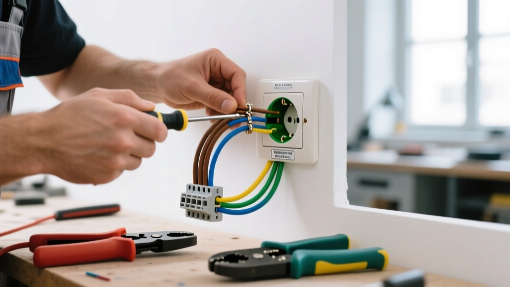
- Wire: H07V-U (rigid copper) or H07V-R (stranded) 2.5mm². Colors: Brown (Phase), Blue (Neutral), Green/Yellow (Earth).
- Flush-Mounting Box (Boîte d'Encastrement): Standard 67mm depth Batibox (Ref: 89302) for drywall or masonry.
- Circuit Protection: 20A maximum miniature circuit breaker (MCB) with a 30mA Type AC or Type A residual current device (RCD / Interrupteur Différentiel) upstream.
- Testing Equipment: Category III or IV Voltage Absence Tester (VAT), such as the Chauvin Arnoux C.A 745, and a digital multimeter.
NF C 15-100 Minimum Outlet Requirements by Room
Before pulling new wires, verify that your circuit design meets the minimum outlet density required by the latest amendments to the French code. A single 20A circuit protected by 2.5mm² wire can support a maximum of 8 standard outlets.
| Room Type | Minimum Outlets (Standard) | Specialized Outlets Required | Max Outlets per 20A Breaker |
|---|---|---|---|
| Living Room (Séjour) | 5 (or 1 per 4m²) | 1x RJ45 (Grade 2 TV/Data) | 8 |
| Kitchen (Cuisine) | 6 (including 4 over worktop) | 1x 32A (Cooktop), 1x 20A (Dedicated) | 8 (Excluding dedicated) |
| Bedroom (Chambre) | 3 | None | 8 |
| Bathroom (Salle d'Eau) | 1 (Near mirror, specific zones) | 1x Shaver socket (optional) | N/A (Strict volume zones) |
Step-by-Step Installation Procedure
Step 1: Isolate the Circuit and Verify Zero Voltage
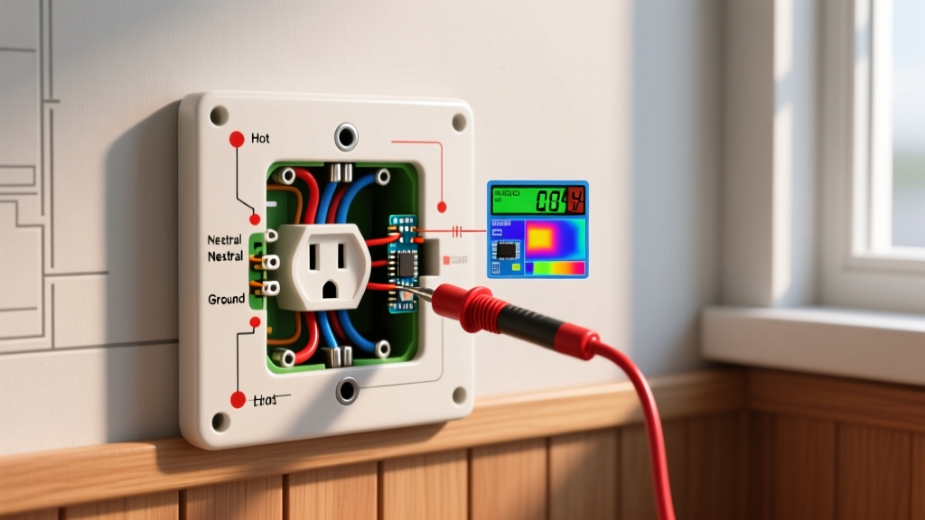
Locate your main distribution board (Tableau Électrique) and switch off the 20A MCB corresponding to the outlet circuit. Never rely solely on the breaker toggle position. Use your CAT III VAT tester to verify the absence of voltage at the existing wires or at the breaker terminals. Test between Phase and Neutral, Phase and Earth, and Neutral and Earth. As outlined by Service-Public.fr, rigorous verification is a legal prerequisite for any electrical modification in French dwellings to prevent fatal 230V arc flashes.
Step 2: Prepare the Flush-Mounting Box (Boîte d'Encastrement)
If you are installing into plasterboard (Placo), use a 68mm hole saw to cut the opening. Insert the 67mm deep Batibox and secure it using the integrated drywall claws (griffes). For masonry walls, embed the box using plaster or rapid-setting cement, ensuring the front edge sits perfectly flush with the finished wall surface. A recessed box will prevent the faceplate from seating correctly, while a protruding box will leave an unsightly gap.
Step 3: Strip and Route the 2.5mm² Conductors
Feed the 2.5mm² H07V-U cable into the box, leaving about 150mm (6 inches) of working length. Using a precision wire stripper, remove exactly 12mm of insulation from the ends of the brown, blue, and green/yellow wires. Do not nick the copper conductor, as this creates a micro-fracture that can lead to localized heating and eventual failure under a 16A load.
Step 4: Terminate the Type E Mechanism
Modern Legrand and Schneider mechanisms often feature push-in auto-clamp terminals alongside traditional screw terminals. If using screw terminals, follow this specific sequence to ensure safety and mechanical stability:
- Earth (Terre): Insert the Green/Yellow wire into the terminal marked with the earth symbol (⏚) or colored green. Tighten to 1.2 Nm. This must always be connected first and disconnected last.
- Neutral (Neutre): Insert the Blue wire into the terminal marked 'N'. While NF C 15-100 does not strictly enforce left/right polarity for standard sockets, maintaining Phase on the right and Neutral on the left (when facing the socket) is the universal French best practice.
- Phase (Phase): Insert the Brown (or Red/Black in legacy systems) wire into the terminal marked 'L'.
Gently tug each wire to ensure a solid mechanical grip. Ensure no bare copper is exposed outside the terminal housing.
Step 5: Mount, Level, and Energize
Carefully fold the wires into the 67mm box using a zig-zag pattern to avoid pinching the insulation against the metal mounting yoke. Secure the mechanism to the box using the provided M3.5 mounting screws. Use a spirit level to ensure the yoke is perfectly horizontal before tightening the claws. Snap on the finishing faceplate. Restore power at the MCB and test the receptacle using a French-standard plug tester to verify correct wiring and RCD trip functionality.
Troubleshooting Common French Wiring Edge Cases
Earth Pin Continuity Failure
The most common failure mode in older French renovations is a missing or high-resistance earth connection. The Type E socket relies entirely on the protruding pin for grounding. If your multimeter reads infinite resistance between the socket's earth pin and the main distribution board's earth bar, the circuit is non-compliant. Solution: You must pull a new 2.5mm² earth wire back to the panel, or install a local earth rod (Piquet de terre) with a 100-ohm maximum resistance, though pulling a new continuous wire is the only code-compliant fix for standard circuits.
Shallow Wall Cavities and 50mm Boxes
In some older French stone buildings or specific partition walls, you may encounter 50mm shallow flush boxes. Standard 2.5mm² rigid wire is incredibly difficult to fold into a 50mm depth behind a bulky socket mechanism. Solution: Switch to H07V-R (stranded/flexible) 2.5mm² wire, which is vastly more pliable. Alternatively, use a shallow-depth socket mechanism specifically designed for 40mm/50mm boxes, such as the Schneider Electric Odace shallow series, which reduces the rear protrusion by 30%.
Upgrading to Smart Outlets (2026 Perspective)
With the rise of Matter and Zigbee home automation in 2026, many DIYers are replacing standard Type E mechanisms with smart equivalents like the Legrand Netatmo Connected Outlet (Ref: 067776). When installing these, ensure your flush box is at least 50mm deep to accommodate the internal relay module, and verify that your circuit includes a physical Neutral wire (Blue), which is mandatory for 99% of smart receptacles to power their internal radios without causing ghost-voltage flickering on the line.