
Understanding the SAE J286 7-Way RV Blade Standard
When towing heavy loads, RVs, or horse trailers, the standard 4-way flat connector falls short. The wiring diagram for 7 way trailer plug configurations (governed by the SAE J286 standard for RV blade connectors) introduces three critical circuits: 12V auxiliary power, electric brake control, and reverse lights. However, the addition of these circuits exponentially increases the complexity of diagnosing electrical faults. In modern 2024–2026 tow vehicles, Body Control Modules (BCMs) utilize Pulse Width Modulation (PWM) for lighting circuits, meaning traditional analog test lights are virtually useless for diagnosis. This guide provides a master pinout reference and a professional-grade diagnostic workflow to isolate faults in your 7-way trailer wiring.
Standard 7-Way RV Blade Pinout Matrix
Before testing, you must verify the physical pinout. The standard RV 7-way blade connector is viewed from the back of the vehicle socket or the front of the trailer plug. Wire gauges listed below are minimum requirements for runs under 25 feet; for longer trailers, step up one gauge size to mitigate voltage drop.
| Clock Position | Pin Function | Standard Wire Color | Min. Wire Gauge | Typical Voltage / Signal |
|---|---|---|---|---|
| 12:00 (Top) | Left Turn / Stop | Yellow | 14 AWG | 12V DC (PWM on newer trucks) |
| 2:00 | Reverse Lights | Purple | 14 AWG | 12V DC |
| 5:00 | Ground (Chassis) | White | 12 AWG (or 10 AWG) | 0V (Return Path) |
| 7:00 | Right Turn / Stop | Green | 14 AWG | 12V DC (PWM on newer trucks) |
| 9:00 | Tail / Running Lights | Brown | 14 AWG | 12V DC |
| 10:00 (Center-Left) | Electric Brakes | Blue | 10 AWG | 0V to 12V DC (Variable) |
| 2:00 (Center-Right) | 12V Auxiliary / Battery Charge | Black | 10 AWG | 12V to 14.4V DC (Constant) |
Note: Always verify your specific vehicle manufacturer's wiring diagram, as some European imports or custom commercial rigs may deviate from the standard North American RV blade color codes. For comprehensive OEM schematics, consult etrailer's comprehensive wiring guide.
Essential Diagnostic Toolkit for 2026 Tow Vehicles
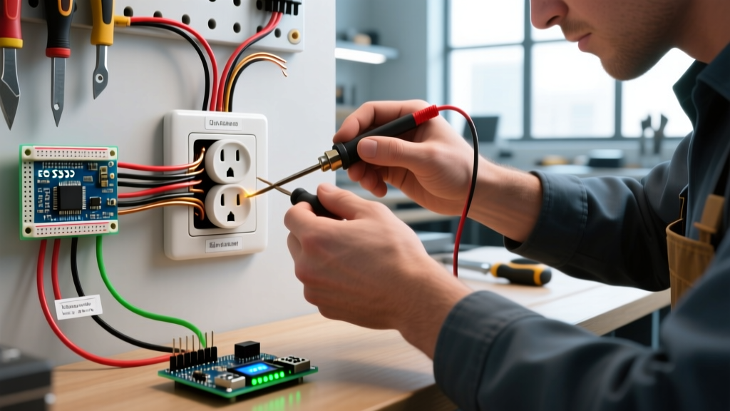
Diagnosing a 7-way plug on a modern truck requires tools that can read high-frequency PWM signals and detect micro-voltage drops. Throw away the $5 incandescent test light; it will not trigger a modern BCM and may even cause the truck to throw a trailer lighting fault code.
- Digital Multimeter (True RMS): The Fluke 117 ($220) or Klein Tools MM400 ($55). True RMS is mandatory for accurately reading PWM taillight circuits.
- Electronic Circuit Tester: The Hopkins 40375 ($18) features high-impedance LED testing that safely interfaces with modern multiplexed vehicle wiring.
- Ratcheting Crimper & Adhesive Heat Shrink: For repairs, use a Titan 11610 ratcheting crimper and 3M MDS 3:1 adhesive-lined heat shrink tubing to ensure waterproof, vibration-proof seals.
- Dielectric Grease: Permatex 22058 ($8) to prevent galvanic corrosion inside the blade receptacle.
Step-by-Step Troubleshooting Flow
Phase 1: Ground Fault Isolation (The 80% Rule)
Over 80% of all trailer wiring anomalies—ranging from flickering running lights to electric brakes locking up randomly—are caused by a compromised ground. The white wire (Pin 5) must have a zero-resistance path to the tow vehicle's chassis and the trailer's chassis.
- Test the Vehicle Side: Set your multimeter to DC Volts. Place the black probe on a known clean metal point on the truck's bumper or frame (not the socket housing). Place the red probe on the 5:00 ground pin of the vehicle socket. Have a helper turn on the running lights and apply the manual brake controller slide. If you read any voltage above 0.1V, your truck-side ground is compromised.
- Test the Trailer Side: Disconnect the trailer. Splice a temporary 12 AWG jumper wire directly from the trailer's white ground wire to the truck's bare frame. If all lighting and brake issues instantly resolve, your trailer's ground ring terminal is corroded, or it is bolted to painted steel rather than bare metal.
Phase 2: Voltage Drop & Backfeed Testing
If the ground is solid but your trailer battery isn't charging, or your electric brakes feel weak, you are experiencing voltage drop. According to Hopkins Manufacturing trailer wiring standards, heavy-load circuits (brakes and 12V auxiliary) should not exceed a 0.5V drop under full load.
- Testing the Blue (Brake) Wire: Connect the trailer. Engage the manual override on your brake controller (e.g., Tekonsha Prodigy P3) to maximum output (12V). Measure voltage at the truck's 7-way socket (Pin 10). Then, measure voltage at the trailer's brake magnets. If the socket reads 12.5V but the magnets only receive 10.2V, you have a 2.3V drop. This indicates undersized wiring, a corroded inline fuse holder, or a failing breakaway switch.
- Testing the Black (Auxiliary) Wire: Measure Pin 2 (12V Aux) at the socket with the truck running (should be ~13.8V to 14.2V). Plug in the trailer and measure at the trailer's battery positive terminal. A drop below 12.5V means the 10 AWG wire is insufficient for the distance, or the truck's factory battery charge relay is faulty (a common issue in 2021–2025 GM Silverado/Sierra models).
Phase 3: Diagnosing BCM Hyperflash and LED Backfeed
Modern trucks monitor trailer lighting circuits for continuity. If you have upgraded your trailer to LED lights, the current draw is so low (often <0.2A per lamp) that the truck's BCM assumes a bulb is blown, resulting in hyperflashing turn signals or a "Trailer Wiring Fault" dashboard warning.
Expert Diagnostic Tip: Never splice standard 50W ceramic load resistors directly into trailer wiring harnesses to fix BCM hyperflash. They generate massive heat and can melt trailer wiring insulation. Instead, install specialized PWM-compatible trailer lighting modules (like the Optronis Smart Tow modules) that simulate incandescent load signatures without generating excess thermal energy.
Common Failure Modes & Edge Cases
| Symptom | Probable Cause | Diagnostic Action |
|---|---|---|
| Trailer running lights illuminate when truck brake is applied. | Short circuit between Brown (Tail) and Yellow/Green (Stop) wires, usually at the trailer tongue flex point. | Perform continuity test between Pin 9 and Pin 1/7 at the trailer plug with all bulbs removed. |
| Brakes lock up fully when headlights are turned on. | Massive ground fault. The brake current is backfeeding through the tail light circuit to find a ground. | Clean and re-terminate the main white ground ring terminal on the trailer frame. |
| Reverse lights on trailer stay illuminated while driving forward. | Purple wire shorted to Black (12V constant) inside the 7-way plug housing due to melted insulation. | Open the 7-way plug housing and inspect for pinched wires behind the strain relief boot. |
Repair Protocol: Crimping vs. Soldering in High-Vibration Environments
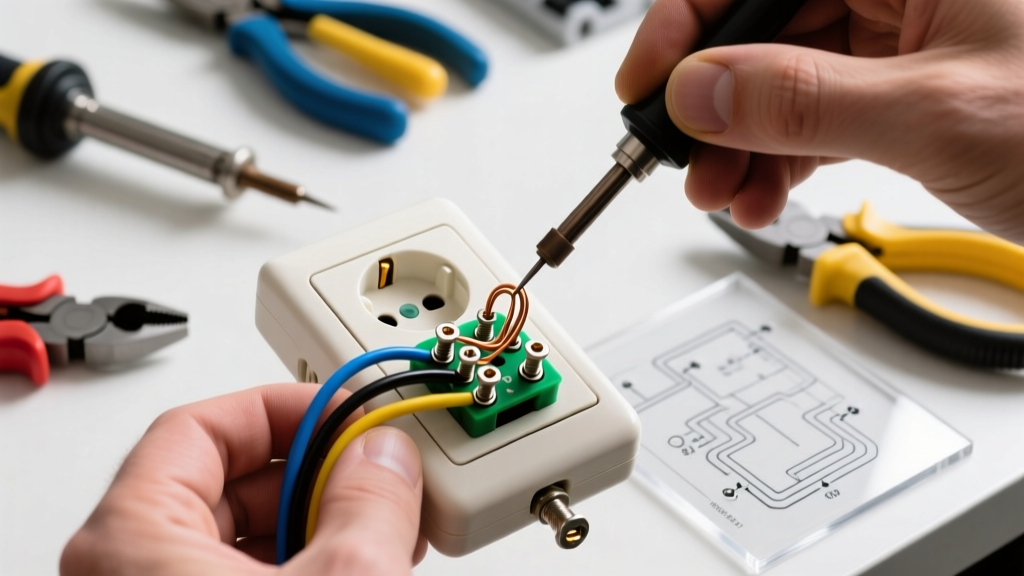
A common DIY mistake when repairing a severed 7-way cable is using rosin-core solder. While solder is excellent for static PCB electronics, trailer wiring is subjected to extreme high-frequency vibration, torsional twisting at the tongue, and thermal cycling. Soldered joints become brittle and will eventually micro-crack, leading to intermittent resistance and voltage drop.
The Professional Repair Standard:
- Strip and Slide: Strip 3/8" of insulation. Slide a piece of 3:1 adhesive-lined marine heat shrink over the wire before crimping.
- Use Ratcheting Crimpers: Use a ratcheting crimper calibrated for non-insulated terminals (like the Titan 11610). The ratchet ensures the exact compression force is applied, cold-welding the copper strands to the brass terminal without crushing the wire.
- Seal with Heat: Slide the adhesive-lined heat shrink over the crimp barrel and apply heat with a heat gun (not a lighter) until the adhesive bubbles out the ends. This creates a 100% waterproof seal, preventing the green copper oxide corrosion that destroys 7-way plugs over time.
- Apply Dielectric Grease: Pack the interior of the replacement 7-way plug housing (such as the Hopkins 48138 or Pollak PK11893, both retailing around $18–$24) with dielectric grease to displace moisture and prevent galvanic corrosion between the brass pins and copper wire.
By strictly adhering to the SAE J286 pinout, utilizing True RMS diagnostic tools, and executing vibration-proof crimped repairs, you can eliminate the most persistent 7-way trailer wiring faults and ensure safe, reliable towing.