
Understanding Japan's Unique Electrical Infrastructure
Inspecting and testing an electrical outlet in Japan requires a fundamental shift in perspective for electricians and DIYers accustomed to North American or European grids. While Japan primarily utilizes the Type A (two flat parallel pins) and Type B (two flat pins plus a grounding pin) receptacles, the underlying infrastructure operates on a unique 100V nominal standard with a bifurcated frequency grid. Whether you are an expat setting up a home workshop, a traveler importing high-draw appliances, or a technician troubleshooting a vintage Japanese property, rigorous inspection is mandatory.
According to the International Electrotechnical Commission (IEC), Japan's Type A outlets share physical dimensions with North American NEMA 1-15R receptacles. However, the Japanese Industrial Standards (JIS C 8303) dictate stricter manufacturing tolerances and material requirements for domestic receptacles. This guide provides a comprehensive, step-by-step protocol for inspecting, testing, and troubleshooting Japanese electrical outlets in 2026.
The 100V Standard and the 50/60Hz Divide
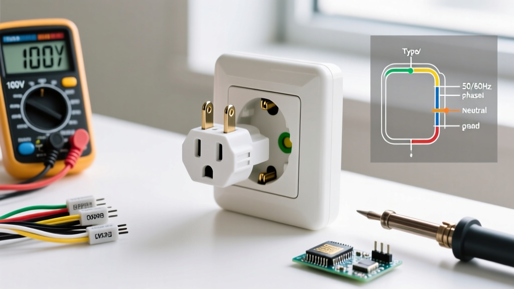
Unlike the 120V standard in the US or the 230V standard in Europe, Japan operates on a 100V nominal voltage. The acceptable tolerance under normal grid conditions is typically ±6V (94V to 106V). Plugging a standard 120V North American appliance into a Japanese outlet will result in a 16.6% voltage drop, which can cause motors to overheat and heating elements to underperform.
Furthermore, Japan is the only major industrialized nation with two different grid frequencies:
- 50Hz: Eastern Japan (Tokyo, Yokohama, Tohoku, Hokkaido). Historically sourced from AEG (Germany).
- 60Hz: Western Japan (Osaka, Kyoto, Nagoya, Kyushu). Historically sourced from General Electric (US).
When testing an outlet, verifying the local frequency is critical if you are operating induction motors, analog timing devices, or specialized medical equipment.
Essential Testing Equipment for Japanese Outlets
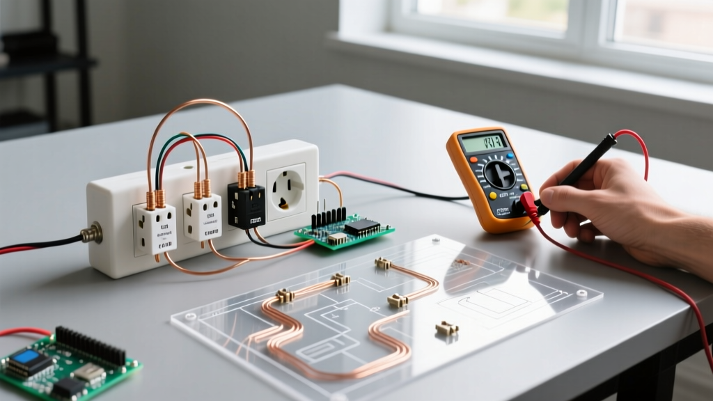
To perform a thorough inspection, you must move beyond basic neon receptacle testers. Equip yourself with the following professional-grade tools:
- True-RMS Digital Multimeter with Frequency: The Sanwa CD800a (approx. ¥4,500 / $30 USD) is a domestic favorite, but for advanced diagnostics, the Fluke 117 ($180 USD) offers superior non-contact voltage (NCV) detection and precise Hz readouts.
- Insulation Resistance Tester (Megohmmeter): The Hioki 3124 (approx. ¥35,000 / $230 USD) is essential for testing the integrity of aging wiring in older Japanese wooden homes (moya).
- Earth Resistance Tester: Required for verifying the separate grounding terminals found in Japanese wet areas.
Step-by-Step Inspection and Testing Protocol
Phase 1: Visual and Mechanical Inspection
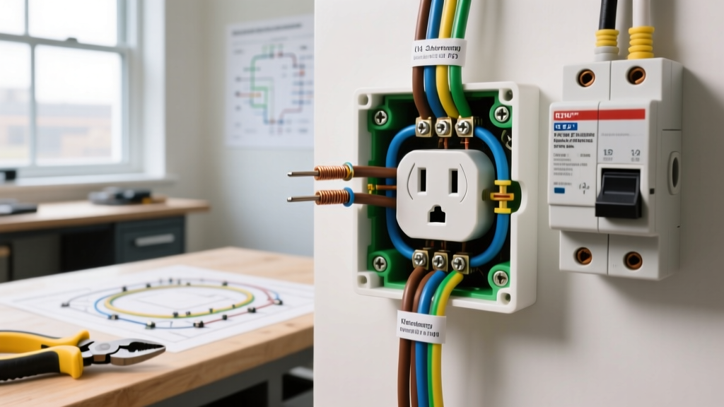
Before applying power, de-energize the circuit at the Bunken-ban (distribution board) and inspect the physical receptacle.
- PSE Mark Verification: Check the outlet casing for the Diamond PSE (Product Safety Electrical Appliances and Materials) mark. The Ministry of Economy, Trade and Industry (METI) mandates this mark for all Category A electrical components sold in Japan.
- Pin Tension Test: Insert a standard Type A plug. Japanese JIS standards require specific retention forces. If the plug slides in with zero resistance, the internal phosphor bronze contacts are fatigued, posing a severe arc-flash risk under high continuous loads (e.g., space heaters).
- Shutter Mechanisms: Modern Japanese outlets, especially in homes built post-2010, feature internal safety shutters. Verify that both shutters open simultaneously when equal pressure is applied to both pins.
Phase 2: Live Voltage, Polarity, and Frequency Testing
Re-energize the circuit and set your True-RMS multimeter to AC Voltage.
- Line to Neutral (L-N): Insert the probes into the two vertical slots. The reading must be between 94V and 106V. (Note: The wider slot is Neutral, the narrower is Line, though reverse polarity is a common fault in pre-1980s Japanese wiring).
- Line to Ground (L-G): Measure from the narrow slot to the grounding pin (if Type B) or the separate earth screw. It should read identical to L-N (approx. 100V).
- Neutral to Ground (N-G): This should read as close to 0V as possible. A reading above 2V indicates a high-resistance neutral connection or an overloaded shared neutral upstream.
- Frequency Check: Switch your multimeter to the Hz function. Probe L-N. Confirm whether the local grid is supplying 50Hz or 60Hz.
Expert Insight: In Japan, the Neutral and Ground are bonded only at the main service entrance. If you measure 50V on N-G, do not assume a split-phase system (like the US 120/240V). You are likely measuring induced phantom voltage from parallel runs in tightly packed Japanese conduit. Use a low-impedance (LoZ) setting on your multimeter to eliminate ghost voltages.
Troubleshooting Matrix: Common Japanese Outlet Faults
| Measured Fault | Symptom | Root Cause in Japanese Grid | Corrective Action |
|---|---|---|---|
| L-N reads 85V - 90V | Appliances cycle slowly; lights dim | Severe voltage drop due to undersized wiring (1.6mm VVF) on a long run from the Bunken-ban. | Upgrade branch circuit to 2.0mm or 2.6mm VVF copper wire. |
| L-N reads 100V, L-G reads 0V | Shocks from metal appliance chassis | Open ground. Common in 2-pin Type A retrofits where the ground wire was simply capped off. | Run a dedicated ground wire back to the distribution board's ground bus. |
| N-G reads 5V - 10V | Audio equipment hums; sensitive IT gear reboots | Shared neutral overload on a multi-wire branch circuit (MWBC) common in Japanese commercial spaces. | Separate neutrals or install a dedicated isolated ground receptacle. |
| Hz reads 50Hz (in Osaka) | Equipment overheats or timing is off | Improper installation of a frequency converter or inverter-based solar system feeding back incorrectly. | Inspect solar inverter grid-tie settings and local transformer taps. |
Grounding Realities: The "Earth" Terminal in Wet Areas
One of the most confusing aspects for foreign electricians testing an electrical outlet in Japan is the grounding setup in kitchens, bathrooms, and laundry rooms. While Type B (3-pin) outlets are becoming standard in new 2026 construction, millions of existing homes rely on a separate, dedicated Earth Terminal (アース端子).
This terminal is usually a small, green, screw-down cover plate located directly below or beside the 2-pin receptacle. To test this grounding point:
- Set your multimeter to AC Voltage and measure between the Line (narrow slot) and the bare copper wire inside the Earth terminal. It must read ~100V.
- Turn off the power and switch to Ohms (Resistance). Measure between the Earth terminal and a known grounded metallic water pipe. The resistance should be minimal.
- For D-Type grounding (required for wet areas in Japan), the ground resistance must be 100 ohms or less. If your earth resistance tester reads higher, the exterior grounding rod has likely corroded or the soil resistivity has increased due to drought conditions.
Testing the Earth Leakage Breaker (ELB)
Unlike North America, which relies heavily on GFCI/AFCI receptacles at the point of use, Japan utilizes a centralized Earth Leakage Breaker (ELB) or Rouden Shadan-ki located in the main distribution board. This device trips when it detects a leakage current of 30mA or more.
Inspection Step: Locate the ELB in the Bunken-ban. Press the yellow or white "Test" button. The breaker must instantly trip, cutting power to the associated circuits. If it fails to trip, or if it takes longer than 0.1 seconds, the mechanical trip solenoid is seized. According to safety guidelines published by the National Institute of Technology and Evaluation (NITE), a failed ELB is a leading cause of fatal electrocution and electrical fires in Japanese residential properties. Replace the ELB immediately.
Importing 120V Appliances: Step-Up Transformer Verification
If you are using a step-up transformer (100V to 120V) to run imported US appliances, you must test the output of the transformer, not just the wall outlet. Cheap, unregulated autotransformers will output 120V only if the input is exactly 100V. If your local grid sags to 92V during peak summer air-conditioning loads, the transformer output will drop proportionally to 110V, potentially damaging sensitive electronics. Always test the secondary side of the transformer under full load using a True-RMS meter to ensure stable voltage delivery.
Summary
Testing an electrical outlet in Japan goes far beyond plugging in a simple polarity checker. It requires an understanding of the 100V tolerance limits, the 50/60Hz regional divide, and the unique JIS grounding methodologies. By utilizing professional True-RMS equipment, verifying PSE compliance, and rigorously testing both the receptacle and the central ELB, you ensure a safe, code-compliant electrical environment tailored to Japan's distinct infrastructure.