
Decoding the Japan Electric Outlet: JIS C 8303 vs. NEMA
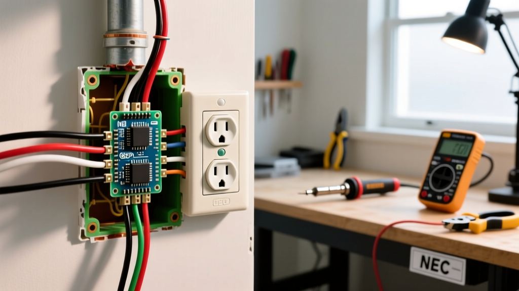
At first glance, a standard japan electric outlet appears physically identical to the North American NEMA 1-15R ungrounded receptacle. Both accept Type A plugs with two flat, parallel pins. However, assuming the underlying wiring diagrams, voltage tolerances, and national safety standards are interchangeable is a critical error that can lead to equipment failure or fire hazards. In Japan, electrical receptacles are governed by JIS C 8303 (Japanese Industrial Standards), which dictates precise dimensional tolerances, material flammability ratings, and internal contact tension specifications that differ subtly but importantly from NEMA standards.
The most fundamental distinction is the nominal voltage. While North American grids deliver 120V (±5%), the Japanese grid operates at a strict 100V (±6V). Furthermore, Japan remains the only country in the world with a dual-frequency grid, split between 50Hz in the east (including Tokyo) and 60Hz in the west (including Osaka). For electricians, DIY enthusiasts, and expatriates wiring a home or importing appliances, understanding these wiring diagrams and the Japanese Electrical Appliance and Material Safety Act (PSE) is mandatory.
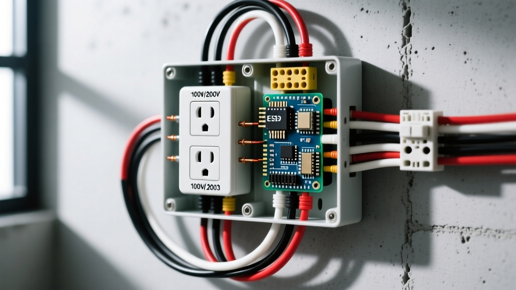
The Single-Phase Three-Wire System (100V/200V)
To understand how a Japan electric outlet is wired at the receptacle level, you must first understand the service drop. Modern Japanese residential electrical panels utilize a single-phase three-wire system (単相3線式, tansō sansen-shiki). This is conceptually similar to the North American split-phase system but operates at different potentials.
- Line 1 (Red): 100V potential relative to Neutral.
- Neutral (White): Grounded center tap (0V).
- Line 2 (Black): 100V potential relative to Neutral, 180 degrees out of phase with Line 1.
Standard 100V receptacles are wired between either Line 1 and Neutral, or Line 2 and Neutral, distributing the 100V load evenly across the panel to prevent transformer imbalance. High-power appliances, such as EcoCute heat-pump water heaters and IH (Induction Heating) cooktops, utilize 200V receptacles wired directly across Line 1 and Line 2. The 200V outlets utilize entirely different physical configurations (typically JIS C 8303 200V 15A or 20A configurations) to prevent accidental insertion of 100V plugs.
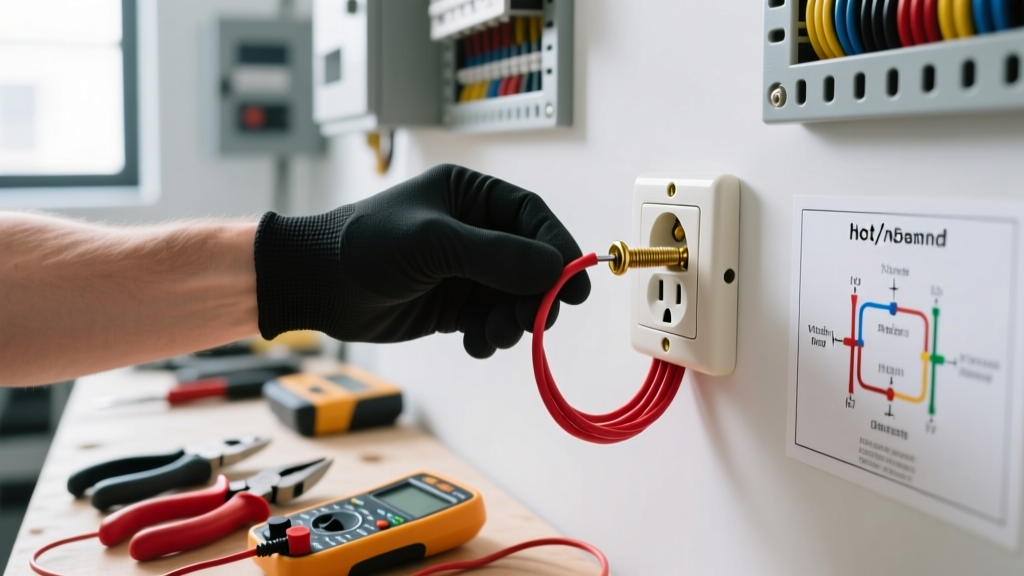
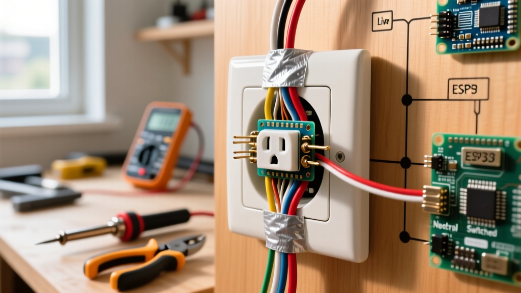
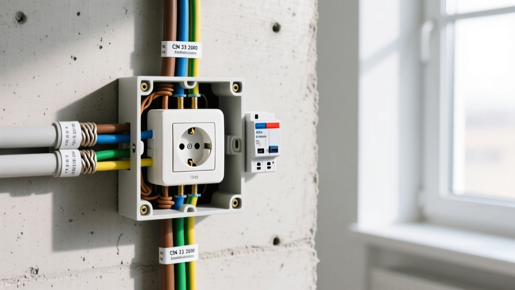
Wiring Diagram Reference: Standard 100V Receptacle Installation
When wiring a standard 100V, 15A Japan electric outlet, the standard cable used in residential construction is VVF (Vinyl Insulated Vinyl Flat) cable. The most common gauges are 1.6mm or 2.0mm diameter solid copper conductors. Unlike North American Romex which uses 14 AWG or 12 AWG stranded/solid wire measured in cross-sectional area, Japanese wire sizing is strictly measured by diameter in millimeters.
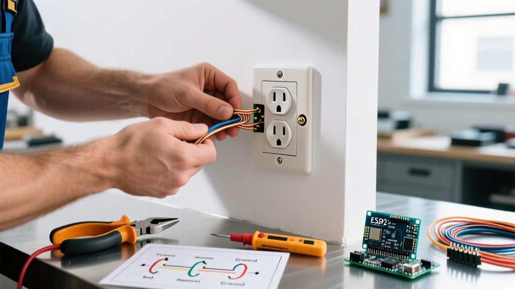
Step-by-Step Wiring Procedure
- Cable Preparation: Strip the outer VVF sheath back approximately 50mm using a specialized cable stripper to avoid nicking the inner PVC insulation. Strip the individual conductor insulation back exactly 12mm to 15mm, depending on the receptacle's terminal depth gauge.
- Identify Conductors: In a standard 2-core VVF cable, the colors are White (Neutral) and Black (Line). If a 3-core cable is used for grounded circuits, the third wire is Green (Ground).
- Terminal Connection: Modern Japanese receptacles (such as the Panasonic Full Color or Cosmo Series) heavily utilize "speed-wire" push-in terminals alongside traditional screw terminals. Insert the stripped Black (Line) wire into the terminal marked with a red dot or the letter 'L'. Insert the White (Neutral) wire into the unmarked terminal or the letter 'N'.
- Verification: Tug gently on each wire to ensure the internal brass clamps have engaged. If using screw terminals, form a clockwise loop and torque to approximately 1.2 Nm to prevent cold-creep loosening over time.
Grounding (Earthing) Requirements: D-Class Grounding
A unique characteristic of the Japan electric outlet landscape is the widespread omission of a ground pin on standard 100V wall receptacles. In most living rooms and bedrooms, only 2-prong ungrounded outlets are installed. However, Japanese electrical codes strictly mandate grounding for specific high-risk environments and appliances.
For washing machines, refrigerators, microwaves, and any outlet located within 2 meters of a water source (bathrooms, kitchens), a ground connection is legally required. This is achieved either through a 3-prong receptacle or a standard 2-prong receptacle paired with an external D-class grounding terminal (a small, green, screw-down lug mounted on the wall plate).
Technical Standard: Under Japanese Electrical Wiring Code, D-Class grounding work (D種接地工事) requires a ground rod driven into the earth with a grounding resistance of 100 ohms or less, and a ground wire diameter of at least 1.6mm. This is critical for triggering Earth Leakage Breakers (ELB) in the event of a fault.
Navigating the 50Hz / 60Hz Regional Divide
When planning electrical loads or importing motor-driven appliances, the regional frequency divide is a vital consideration. The Fuji River and Itoigawa-Shizuoka Tectonic Line roughly divide Japan's grid. Eastern Japan (Tokyo, Tohoku, Hokkaido) operates at 50Hz, a legacy of early German AEG generator imports. Western Japan (Osaka, Nagoya, Kyushu) operates at 60Hz, stemming from early American GE generator imports.
While modern switching power supplies (laptops, phone chargers, LED drivers) handle 50/60Hz seamlessly, AC motors in older air conditioners, fans, and analog clocks will run 20% slower or faster if moved across the frequency divide. Furthermore, the wiring diagrams for heavy inductive loads must account for the differing impedance and voltage drop characteristics inherent to 50Hz versus 60Hz transmission.
Data Matrix: Japan vs. North American Electrical Specs
| Specification | Japan (JIS C 8303) | North America (NEMA / NEC) |
|---|---|---|
| Nominal Voltage | 100V (±6V) | 120V (±5%) |
| Frequency | 50Hz (East) / 60Hz (West) | 60Hz (Universal) |
| Standard Receptacle | Type A (2-prong, 15A) | Type A / Type B (15A / 20A) |
| Residential Wire Sizing | 1.6mm / 2.0mm diameter (VVF) | 14 AWG / 12 AWG cross-section |
| Mandatory Breaker Type | ELB (Earth Leakage Breaker) | GFCI / AFCI (Branch circuit specific) |
| Grounding Prevalence | Rare in living spaces; Mandatory in wet areas | Universal (Type B standard) |
Sourcing PSE-Certified Components
When wiring or replacing a Japan electric outlet, it is illegal and highly dangerous to install non-certified foreign components. All electrical materials installed in Japan must bear the PSE (Product Safety Electrical Appliances and Materials) mark. The PSE mark comes in two forms:
- Diamond PSE Mark: Reserved for "Specified Electrical Appliances and Materials" (Category A), which includes high-risk items like circuit breakers, ELBs, and specific power cables.
- Circle PSE Mark: Used for "Non-Specified Electrical Appliances and Materials" (Category B), which includes standard wall receptacles, switches, and basic lighting fixtures.
Always source receptacles from established domestic manufacturers such as Panasonic, Toshiba, or JELITO. To verify component safety standards and review the latest compliance updates regarding JIS C 8303 receptacles, electricians should consult the Japan Industrial Standards Committee (JISC). Furthermore, safety recalls and hazard data regarding faulty wiring or non-compliant imported outlets are regularly published by the National Institute of Technology and Evaluation (NITE). For third-party testing and certification verification of imported electrical gear, the Japan Electrical Safety & Environment Technology Laboratories (JET) remains the premier authoritative resource.
Final Safety Considerations
Before terminating any wires on a Japanese receptacle, ensure the branch circuit is protected by an Earth Leakage Breaker (ELB) rated at 30mA sensitivity and a trip time of 0.1 seconds or less. Since the 2005 revision of the Japanese Electrical Wiring Code, ELBs are mandatory for all residential circuits to protect against fatal ground faults, compensating for the lack of physical ground pins on many standard 100V outlets. Always verify the absence of voltage with a calibrated digital multimeter before initiating any wiring modifications.